


2. Wiring and Connection
2 - 1
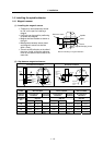
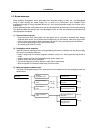
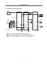
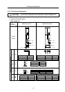
2-1 Part system connection diagram........................................................................................................ 2-3
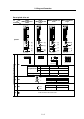
2-2 Main circuit terminal block/control circuit connector .......................................................................... 2-4
2-2-1 Names and applications of main circuit terminal block signals and control circuit connectors... 2-4
2-2-2 Connector pin assignment .......................................................................................................... 2-5
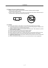
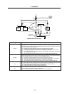
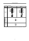
2-3 NC and drive unit connection............................................................................................................. 2-8
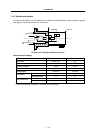
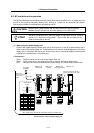
2-4 Motor and detector connection......................................................................................................... 2-11
2-4-1 Connecting the servomotor ....................................................................................................... 2-11
2-4-2 Connecting the full-closed loop system..................................................................................... 2-18
2-4-3 Connecting the synchronous control system ............................................................................ 2-22
2-4-4 Connection of the spindle motor ............................................................................................... 2-28
2-5 Connection of power supply............................................................................................................. 2-33
2-5-1 Power supply input connection .................................................................................................. 2-34
2-5-2 Connecting the grounding cable ............................................................................................... 2-37
2-5-3 Main circuit control ..................................................................................................................... 2-38
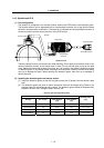
2-6 Wiring of the motor brake................................................................................................................. 2-39
2-6-1 Wiring of the motor magnetic brake .......................................................................................... 2-39
2-6-2 Dynamic brake unit wiring ......................................................................................................... 2-41
2-7 Peripheral control wiring.................................................................................................................... 2-42
2-7-1 Input/output circuit wiring............................................................................................................ 2-42
2-7-2 Spindle coil changeover ............................................................................................................ 2-43
2-7-3 Wiring of an external emergency stop....................................................................................... 2-46