


3. Setup
3 - 3
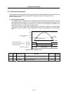
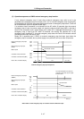
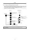
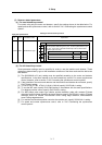
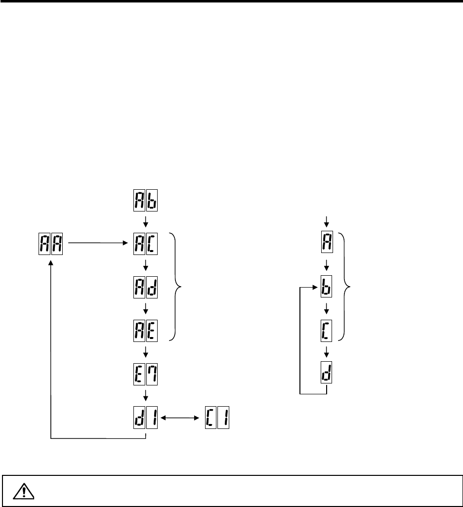
3-1-2 Transition of LED display after power is turned ON
When CNC, each drive unit and the power supply unit power have been turned ON, each unit will
automatically execute self-diagnosis and initial settings for operation, etc. The LEDs on the front of the
units will change as shown below according to the progression of these processes.
If an alarm occurs, the alarm No. will appear on the LEDs. Refer to "6-1 LED display when alarm or
warning occurs" for details on the alarm displays.
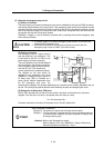
CAUTION
Always input emergency stop when starting the servo system.
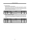
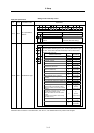
Executing initial
communication with NC
Drive unit initialization complete
Waiting for NC power start up
Emergency stop state
The LED will alternate between
F# → E7 → not lit.
(# is the set axis No.)
Repeats lighting and going out.
(1st axis in the display example)
NC power ON
Waiting for NC
power start up
NC power OFF
NC power ON
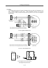
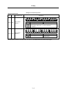
LED display
Servo ON state Servo OFF sate
Drive units
Executing initial communication
with NC
A : Initializing
b : Ready OFF, in emergency stop
c : Ready ON/servo OFF
Emergency stop state
NC power
ON
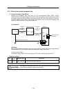
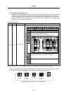
LED display
Servo ON state
Power supply unit