


3. Tool Offset (L system)
3.1 Wear Data
I-78
Refer to "3 (II). Tool Offset (M system)" for M system.
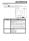
3.1 Wear Data
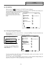
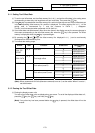
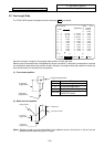
The TOOL TIP OFFSET screen will appear when the menu key
T-OFSET
is pressed.
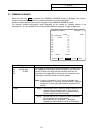
T-OFSET T-DATA NOSE-R LIFE MENU
[TOOL TIP OFFSET] TOOL 1.1/4
[POSITION] X 0.000
#I :INC. #A :ABS. Z 0.000
# C 0.000
1 X 0.050 Z 0.020 C 0.100
2 X 0.100 Z 0.050 C 0.010
3 X 0.000 Z 0.000 C 0.000
4 X 0.000 Z 0.000 C 0.000
5 X 0.000 Z 0.000 C 0.000
6 X 0.000 Z 0.000 C 0.000
7 X 0.000 Z 0.000 C 0.000
8 X 0.000 Z 0.000 C 0.000
9 X 0.000 Z 0.000 C 0.000
10 X 0.000 Z 0.000 C 0.000
# ( ) X ( ) Z ( ) C ( )
Set the tool nose wear for each tool used. When the tool compensation No. is designated by the tool command (T
command), compensation is carried out matching the tool length of the next screen.
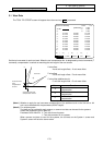
X axis offset
X axis tool length offset + X axis wear offset
Z axis offset
Z axis tool length offset + Z axis wear offset
C axis offset (additional axis)
C axis tool length offset + C axis wear offset
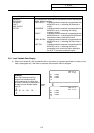
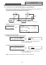
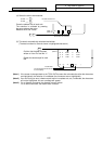
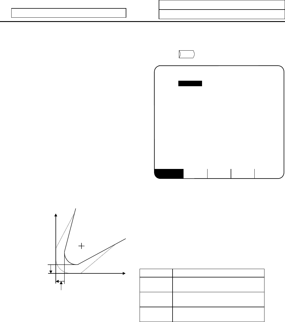
Data Function
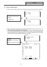
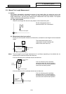
X
X axis tool nose wear
compensation
Z
Z axis tool nose wear
compensation
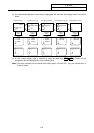
Tool nose
Z axis tool nose wear
compensation amount
X axis tool nose
wear
compensation
amount
Z
X
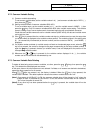
C
Additional axis tool nose wear
compensation
(Note 1) Whether to apply the tool nose wear compensation of the additional axis on the 3rd axis or 4th
axis can be selected with the parameter (#1520 Tchg34).
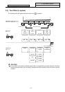
(Note 2) For multiple system
Tool data can be provided for each system, or common tool data can be used for the systems.
Select with parameter (#1501 MemTol).
Parameter #1501 MemTol 0: Tool data for each system
1: Tool data common for all systems
When common tool data is used for the systems, the tool data on the System 1 screen and
System 2 screen will have the same values.