


6. Operation Panel Switch Functions
6.10 Error Detect
II-21
6.10 Error Detect
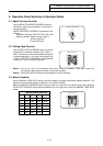
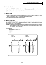
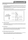
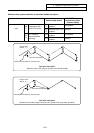
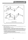
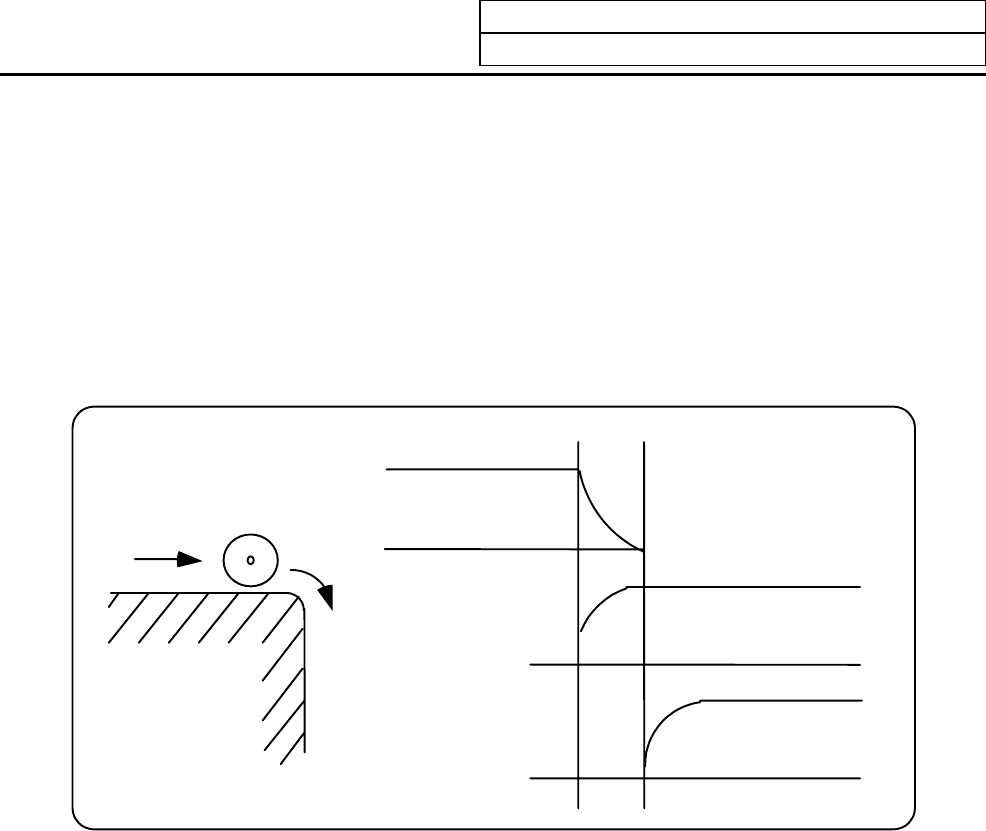
For positioning (G00), machine deceleration check is made before next block move is started. For cutting
(G01, G02, or G03), the next block is started before the machine reaches the move command end point. Thus,
the corner part is slightly rounded.
To prevent rounded corners, turn ON the error detect signal. This will cause the machine to decelerate until
the remaining distance falls below the value of the parameter. The next block command is stopped during this
time.
This function is equivalent to G09 in the program.
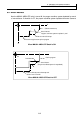
The parameter that is used by the error detect switch and the G09 command for determining the remaining
distance after deceleration for moving to the next command can be set with the settings monitor device.
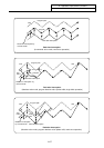
X axis command
Y axis command
Y axis command
Error detect of
f
Error detect on
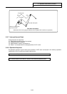
6.11 Follow-up Function
The follow-up function monitors machine motion in the emergency stop state and reflects it in the current
position and workpiece coordinates. Thus, the work program can be continued without again making return
to reference position after emergency stop.
6.12 Axis Removal
When the machine receives the axis removal signal, that axis no longer becomes the controlled axis.
Accordingly, the alarm for the stroke end axis and the servo alarms (excessive errors, lack of signal, drive
alarm, etc.) will be ignored. At the same time, the axis will become interlocked.
(Note) This cannot be used for the absolute position detector specification axis.
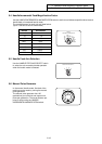
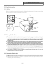
6.13 Manual/Automatic Synchronous Feed
While you are using the automatic operation in the automatic operation mode, you can simultaneously
operate the machine manually (jog, return to reference point, incremental feed, handle).
To select the manual mode and automatic mode, refer to the machine's instruction manual.