


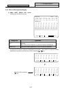
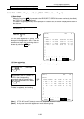
4. Parameters (User)
4.1 Workpiece Coordinate
I-133
# Parameter Explanation Setting range (units)
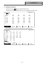
54
55
56
57
58
59
60
101
:
148
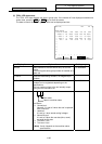
G54 offset
G55 offset
G56 offset
G57 offset
G58 offset
G59 offset
EXT offset
P1
:
P48
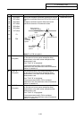
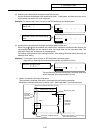
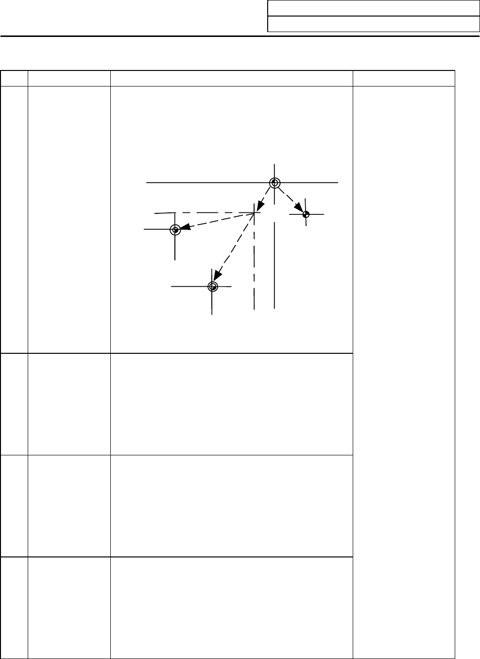
Specify the workpiece coordinate system and external
workpiece coordinate offset from G54 to G59, and P1 to
P48.
Workpiece coordinate system offset data can be
specified in absolute or incremental values.
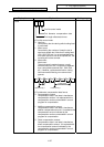
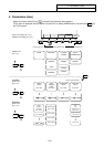
M
R
W2
Basic machine
coordinate system
G55
workpiece
coordinate
system
Reference point
External (EXT)
offset
G54 workpiece
coordinate
system
W1
(Note) P1 to P48 are options.
±99999.999 (mm)
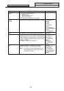
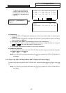
#1 TLM P.A
(M system)
The coordinate value of the measured position (X, Y) of
the first point of he hole center workpiece offset
Measurement or the width center workpiece offset
Measurement is set.
Then “TLM P.A” is highlighted.
If the measurements switch ON or workpiece
coordinate is set, the coordinates value of measured
position is cleared to 0.
#2 TLM P.B
(M system)
The coordinate value of the measured position (X, Y) of
the first point of he hole center workpiece offset
Measurement or the width center workpiece offset
Measurement is set.
Then “TLM P.B” is highlighted.
If the measurements switch ON or workpiece
coordinate is set, the coordinates value of measured
position is cleared to 0.
#3 TLM P.C
(M system)
The coordinate value of the measured position (X, Y) of
the first point of he hole center workpiece offset
Measurement or the width center workpiece offset
Measurement is set.
Then “TLM P.C” is highlighted.
If the measurements switch ON or workpiece
coordinate is set, the coordinates value of measured
position is cleared to 0.