


4. Absolute Position Detection System
4.3 Starting up Absolute Position Detection System
III-25
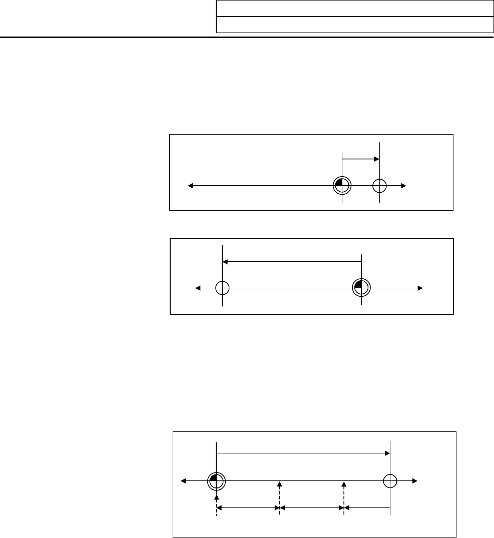
(c) Common precautions for dogless type absolute position detection
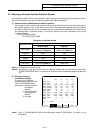
(i) Examples of setting "#2 ZERO" parameter
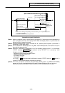
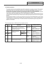
The coordinate value of the absolute basic point (mechanical basic position or electrical basic
position) looking from the basic machine coordinate zero point is set for "#2 ZERO" parameter.
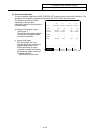
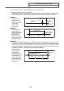
(Example 1)
The zero point is
determined at the
position 50.0 to the
front of the absolute
position basic
position on the
positive side.
Zero point of basic machine
coordinate
"ZERO"=50.0
A
bsolute position
basic point
(Machine basic position
or electrical basic
position)
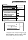
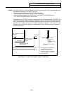
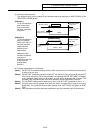
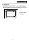
(Example 2)
The zero point is
determined at the
position 400.0mm to
the front from the
machine basic
position or absolute
position basic point at
the negative side.
Zero point of basic
machine coordinate
"ZERO"=-400.0
A
bsolute position
basic
p
oint
(Machine basic position
or electrical basic
position)
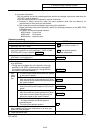
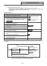
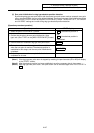
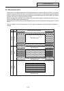
(Example 3)
If it is desired to create the zero point of the basic machine coordinate on a grid point, the value
indicated in "TO END" is used to calculate the value to be set to the "#2 ZERO" parameter as shown
in the example below. The value indicated in "TO END" is the distance from the machine basic
position to the grid point right before the end. (If the coordinates of the absolute position basic point
are used for "#2 ZERO", TO END does not need to be considered.)
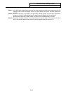
The zero point is
determined at the
third grid point
(10.0mm grid-point
intervals) when "TO
END" indicates −5.3
at the basic position
at the positive side.
(Example for 10.0mm
grid interval.)
Zero point of basic machine
coordinate system
"ZERO"=25.3
Machine basic
position
"TO END" =
–
5.3
10.0 10.0