


4. Parameters (User)
4.2 Machining Parameters
I-157
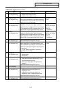
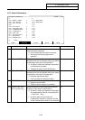
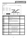
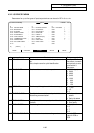
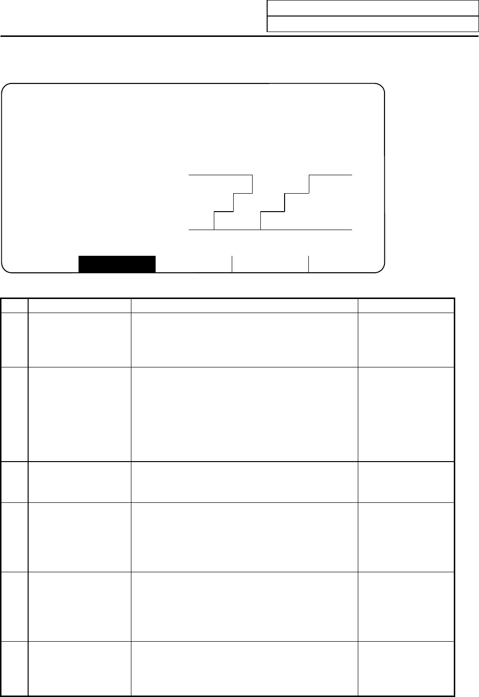
4.2.4 Barrier Data
[BARRIER] PARAM 1.7/8
#
8300 P0 X 0.000
8301 P1 X 0.000 Z 0.000
8302 P2 X 0.000 Z 0.000
8303 P3 X 0.000 Z 0.000
8304 P4 X 0.000 Z 0.000
8305 P5 X 0.000 Z 0.000
8306 P6 X 0.000 Z 0.000
# ( ) X( ) Z( )
WORK
PROCESS I/O PAR SETUP MENU
P1 P4
P2 P5
P3 P6
P0
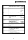
# Item Contents Setup range (unit)
8300 PO
(For L system only)
Set the reference X-coordinates of the chuck and
the tail stock barrier.
Set the center coordinate (Radius value) of
workpiece by the basic machine coordinate system.
±99999.999 (mm)
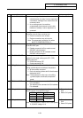
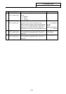
8301
8302
8303
8304
8305
8306
P1
P2
P3
P4
P5
P6
(For L system only)
Set the area of the chuck and tail stock barrier.
(Radius value)
Set the coordinate value from the center of
workpiece for X-axis. Set the coordinate value by
basic machine coordinate system for Z-axis.
±99999.999 (mm)
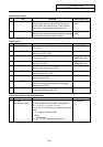
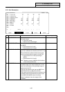
8310 Barrier ON
(For L system only)
Select the validity of the chuck and tailstock barrier.
0: Invalid (Setting from special display unit valid)
1: Valid
0/1
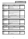
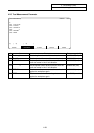
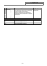
8311
8312
P7
P8
(For L system only)
Set the area of the left spindle section.
• X axis: Set the coordinate value from the
workpiece center (P0). (radius value)
• Z axis: Set the coordinates in the basic
machine coordinate system.
±99999.999 (mm)
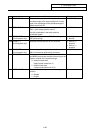
8313
8314
P9
P10
(For L system only)
Set the area of the right spindle section.
• X axis: Set the coordinate value from the
workpiece center (P0). (radius value)
• Z axis: Set the coordinates in the basic
machine coordinate system.
±99999.999 (mm)
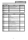
8315 BARRIER TYPE (L)
(For L system only)
Set the shape of the left chuck and tailstock barrier.
0: No area
1: Chuck
2: Tailstock
0/1/2