


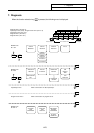

7. Diagnosis
7.2 SERVO MONITOR
I-274
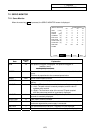
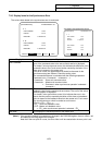
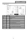
7.2.2 Servo Monitor (2)
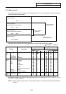
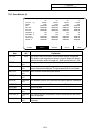
ALARM SERVO SPINDLE PLC-I/F MENU
[SERVO MONITOR(2)] ALARM/DIAGN 2.2/9
<X> <Y> <Z> <C>
CYC CNT (p) 1000000 1000000 1000000 1000000
GRDSP 10.000 10.000 10.000 10.000
GRID -99999.999 -99999.999 -99999.999 -99999.999
MAC POS -99999.999 -99999.999 -99999.999 -99999.999
MOT POS -99999.999 -99999.999 -99999.999 -99999.999
SCA POS -99999.999 -99999.999 -99999.999 -99999.999
FB ERROR (i) -500 -500 -500 -500
DFB COMP (i) -332 -332 -332 -332
DIS TO GO -99999.999 -99999.999 -99999.999 -99999.999
POSITION (2) -99999.999 -99999.999 -99999.999 -99999.999
MANUAL IT -99999.999 -99999.999 -99999.999 -99999.999
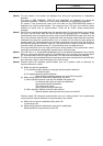
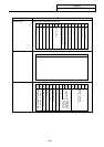
Data
Display
unit
Explanation
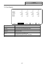
CYC CNT Pulse The position within one rotation of the encoder detector is displayed.
The position uses the grid point value as 0, and will display the position
within one rotation within the range of 0 ~ RNG (movement unit) ∗1000.
GRDSP Command
unit
The grip interval for zero point return is displayed.
GRID Command
unit
The length from the dog-off to grip point when dog-type reference point
return is executed is displayed. The grid mask amount is not included.
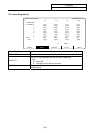
MAC POS Command
unit
Basic machine coordinate system position
MOT POS Command
unit
The feedback position of the speed detector is displayed.
SCA POS Command
unit
The feedback position of the machine end position detector is displayed.
FB ERROR i The error of the motor end FB and machine end FB is displayed.
DFB COMP This is not used.
DIS TO GO Command
unit
The remaining movement distance of one block is displayed.
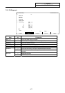
POSITION (2) Command
unit
The value of the tool compensation amount subtracted from the current
value is displayed.
MANUAL IT Command
unit
The amount of interrupt movement in the manual absolute off state is
displayed.