


5. Stored Stroke Limit
5.3 Stored stroke limit IB
III-33
5.3 Stored stroke limit IB
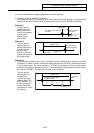
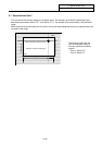
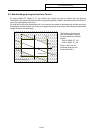
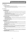
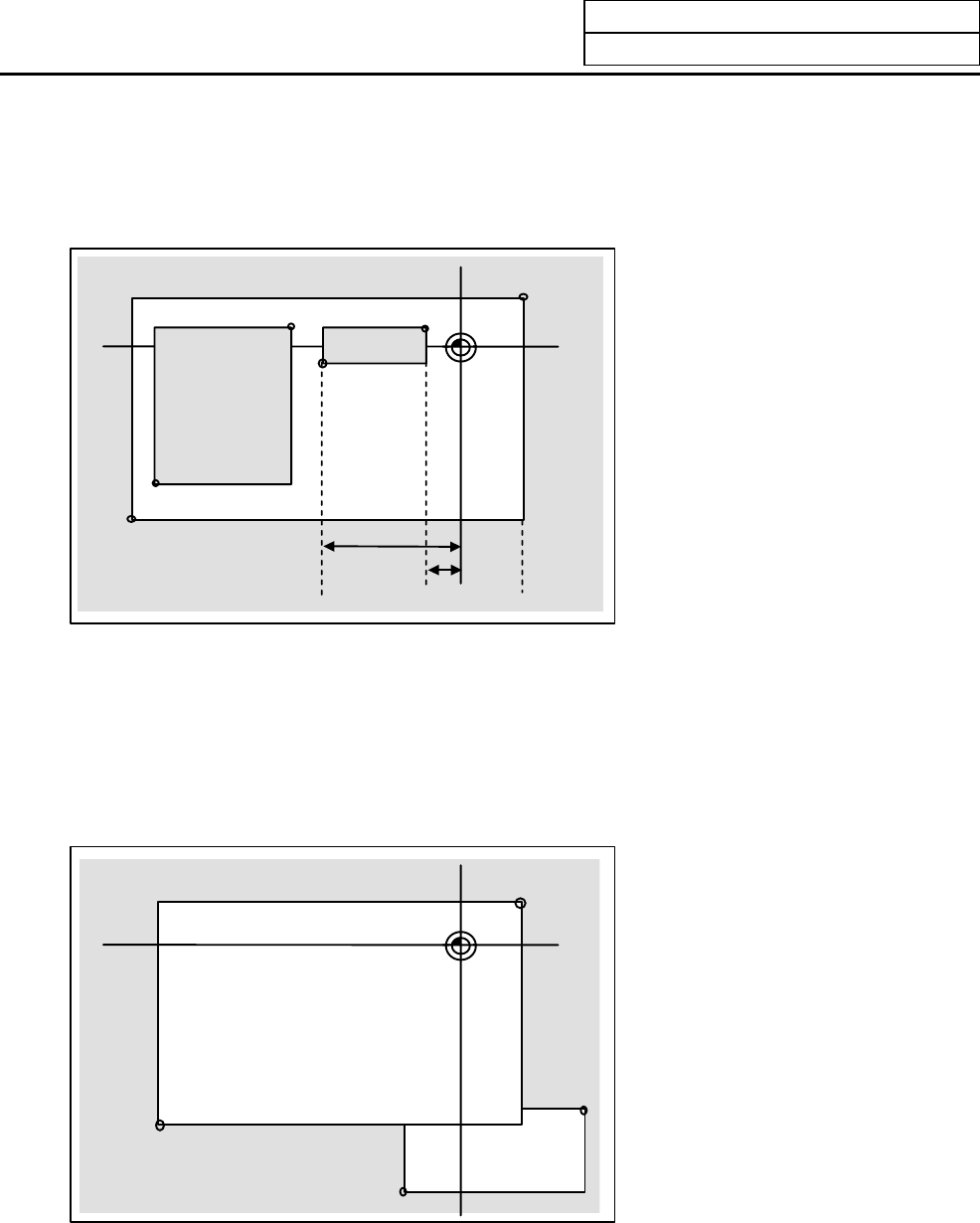
The boundary is set for each axis with the parameters (axis parameters "#2061 OT_1B–" and "#2062
OT_1B+"). The inside of the set boundary is the prohibited range.
Range prohibited
with stored stroke
limit IIB
Basic
machine
coordinate
system
Point 1
Prohibited range
Machine
movement
valid range
– setting value
+ setting value
Prohibited range
Point 2
Point 3
Point 4
Point 6
Point 5
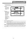
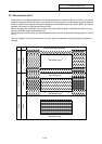
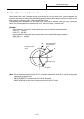
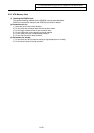
5.4 Stored stroke limit IC
The boundary is set for each axis with the parameters (axis parameters "#2061 OT_1B–" and "#2062
OT_1B+"). The inside of the set boundary is the machine movement valid range.
This is valid when the axis parameter #2063 is set to 2, and cannot be used with soft limit IB.
Basic machine coordinate system
Point 1
Prohibited range
Machine movement valid range
Prohibited range
Point 2
Point 3
Point 4
A
dditional
movement
range
The following values are set
with the coordinate values in
the basic machine coordinate
system.
Point 3 : #2062 OT_1B+
Point 4 : #2061 OT_1B–
Points 1 and 2 are the
prohibited range set with stored
stroke limit I, and points 3 and 4
are the prohibited range set
with stored stroke limit II.
The following values are set
with the coordinate values in
the basic machine coordinate
system.
Point 3 : #2062 OT_1B+
Point 4 : #2061 OT_1B–
Points 1 and 2 are the
prohibited range set with
stored stroke limit I.