


7. Diagnosis
7.2 SERVO MONITOR
I-273
7.2 SERVO MONITOR
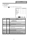
7.2.1 Servo Monitor
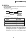
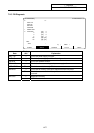
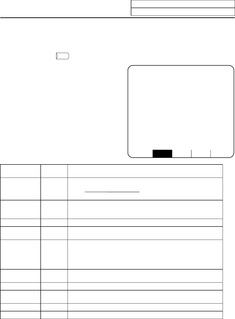
When the menu key
SERVO
is pressed, the SERVO MONITOR screen is displayed.
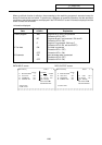
ALARM SERVO SPINDLE PLC-I/F MENU
[SERVO MONITOR] ALARM/DIAGN 2. 1/5
<X> <Y> <Z> <B>
GAIN (1/sec) 0 0 0 0
DROOP (i) 0 0 0 0
SPEED (rpm) 0 0 0 0
CURRENT (%) 2 2 2 0
MAX CUR1 (%) 52 37 29 14
MAX CUR2 (%) 2 2 3 0
OVER LOAD (%) 0 0 0 0
OVER REG (%) 0 0 0 0
AMP DISP D1 D2 D3 C4
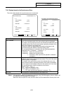
ALARM
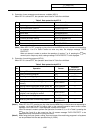
Data
Display
unit
Explanation
GAIN 1/s The position loop gain is displayed. The position loop gain is:
DROOP i An error of the actual machine position to the command position is called
droop.
This error is proportional to the command speed value.
SPEED r/min Actual rotation speed of motor.
CURRENT % The motor current is displayed in terms of continuous current during
stalling.
MAXCUR1 % The current FB ratio to the current limit is shown with a percentage.
1) <Left> The peak value is constantly sampled, and the value is
updated every second.
2) <Right> The maximum value of the current FB peak sampled
after the power was turned on is constantly displayed.
MAXCUR2 % The maximum value of the current FB peak sampled in the last two
seconds is constantly displayed.
OVER LOAD % Data used to monitor overload.
OVER REG % This is the data used to monitor the resistance load state when the
resistance regenerative power supply is connected.
AMP DISP — The same details as the driver's 7-segment LED are displayed.
ALM — The alarms and warnings other than the driver display are displayed.
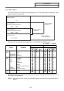
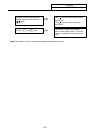
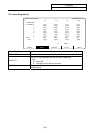
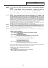
feedrate (mm/s)
tracking delay error (mm)