


2. Monitor
2.2 COORDINATE
I-39
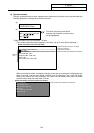
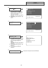
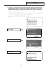
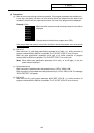
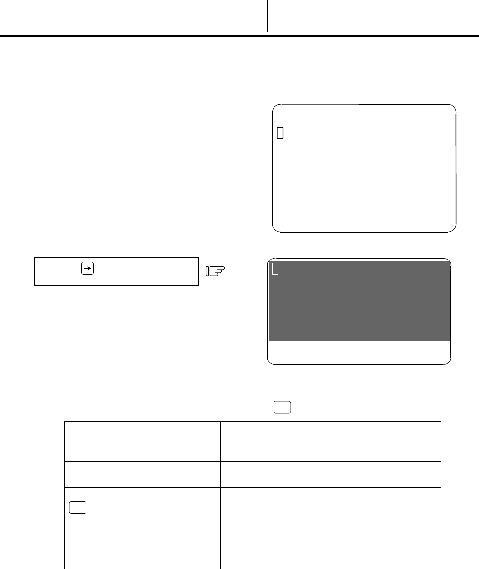
(g) When the buffer correction mode is entered, there may be cases when the program up to ;
(EOB) does not fit in and only part of the program is displayed because the last block displayed
in the buffer correction area is long.
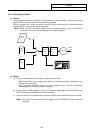
N124 G00 X68. Y201.;
N125 G01 X80. Y195.;
N126 Y150.;
N127 G02 X100. Y185. R20.;
N128 G01 X110.;
N129 G01 Y200.;
N130 G74 X120.0 Y100.0 Z-20.0 R-10.0
P2.,R0;
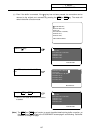
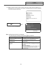
Press the
key.
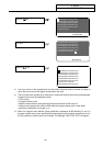
1) "P2.,R0" of N130 is not displayed.
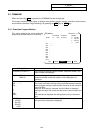
N125 G01 X80. Y195. F50.;
N126 Y150.;
N127 G02 X100. Y185. R20.;
N128 G01 X110.;
N129 G01 Y200.;
N130 G74 X120.0 Y100.0 Z-20.0 R-10.0
BUFFER EDIT
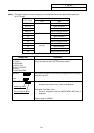
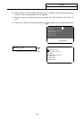
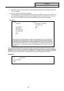
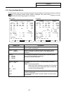
(Note) Handling when entire block is not displayed
The results will differ according to the state when
INPUT
key was pressed.
State Results
; (EOB) is not added to the end of
displayed data.
The section (P2.,R0;) not displayed will be the
continuing part of the displayed section.
; (EOB) is added to the end of the
displayed data.
The section (P2.,R0;) not displayed will become
separate block.
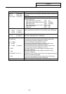
The N130 block is deleted with the
C.B
CAN
key.
During memory/MDI operation:
The section (P2.,R0;) not displayed will also be
deleted.
During tape operation:
Only the displayed section will be deleted, and
the section not displayed will be kept as a
separate block.