


2. Monitor
2.2 COORDINATE
I-30
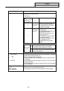
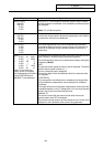
Display item Explanation
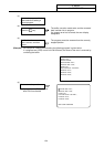
[WORK (G54)]
X -345.678
Y 345.678
Z 0.000
C 0.000
G54~G59, P1~P48 workpiece coordinate system modal numbers
and the workpiece coordinates in the workpiece coordinate system
are displayed.
(Note) P1 to P48 are options.
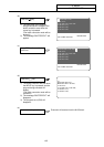
[MACHINE]
X -345.678
Y 345.678
Z 0.000
C 0.000
The coordinate of each axis in the basic machine coordinate system
in which the unique position determined depending on the machine
is used as the zero point are displayed.
[DIS TO GO]
X 0.000
Y 0.000
Z 0.000
C 0.000
The remaining distance of the move command being executed
(incremental distance from the current position to the end point of
the block) is displayed during automatic operation start busy or
pause busy.
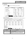
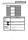
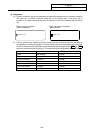
[NEXT]
X1 0.000 S1 5000
Y1 0.000 ( 2000)
Z1 0.000 S2 0
A 0.000 ( 0)
B 0.000 T 1234
C 0.000 M 12
(Note) On the multi-axis
display screen, this display
item corresponds to the area in
which [POSITION B] and
[MANUAL IT] are displayed.
This displays the command contents of the block executed after the
block currently in execution during automatic operation.
The following display items can be selected according to setting the
parameters. (Note1)
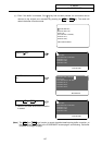
[MST]
The spindle rotation speed command value is displayed. The actual
spindle rotation speed is shown in ( ).
The tool command value is displayed.
The last four digits of the miscellaneous function command value
are displayed.
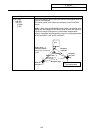
[POSITION B]
Tool nose position coordinate that is considered tool length offset
and tool diameter compensation can be displayed in workpiece
coordinate.
Tool length offset and tool diameter compensation amount that are
considered depend on tool (T) designation or the currently selected
tool No. that is input from the external source.
[MANUAL IT]
The amount moved with the manual mode while the manual
absolute switch was OFF is displayed.
The manual interrupt amount can be selected for the counter value
displayed on the coordinate value screen using parameter.