


3. Tool Offset (M system)
3.1 Tool Offset
I-112
Refer to "3 (I). Tool Offset (L system)" for L system.
3.1 Tool Offset
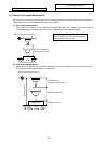
When the menu key
OFFSET
is presented, the TOOL OFFSET screen is displayed.
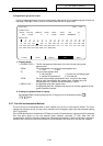
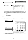
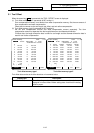
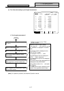
(1) Tool offset memory (type I: parameter #1037 cmdtyp 1)
Form compensation memory is not distinct from wear compensation memory. Set the sum amount of
form compensation and wear compensation.
Offset data is common to the tool length, tool offset, and tool radius compensation.
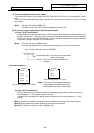
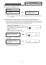
(2) Tool offset memory (type II: parameter #1037 cmdtyp 2)
Set the form compensation amount and wear compensation amount separately. The form
compensation amount is separated into the length dimensions and diameter dimension.
Of offset data, the length dimension data is used for tool length and the diameter dimension data is
used for tool radius compensation.
OFFSET REGIST LIFE NEMU
[TOOL OFFSET] TOOL 1.1/ 2
#A:ABS. #I:INC. [MACHINE] Z 0.000
SURFACE #0 = 50.000
# LENG WEAR RADIUS WEAR
1 120.000 0.020 50.000 0.099
2 100.000 0.004 30.000 0.000
3 100.000 0.000 60.000 0.010
4 20.000 0.005 150.000 0.008
5 20.000 0.530 150.000 0.059
6 300.000 0.032 50.000 0.111
7 250.000 0.000 50.000 0.000
8 150.000 0.006 80.000 0.009
9 200.000 0.000 150.000 0.003
10 500.000 0.667 100.000 0.888
T 0 M
OFFSET REGIST LIFE NEMU
[TOOL OFFSET] TOOL 1.1/ 2
#A:ABS. #I:INC. [MACHINE] Z 0.000
SURFACE #0 = 50.000
#
1 120.000 11 300.000
2 50.000 12 50.000
3 100.000 13 250.000
4 30.000 14 50.000
5 100.000 15 150.000
6 60.000 16 80.000
7 20.000 17 200.000
8 150.000 18 150.000
9 20.000 19 500.000
10 150.000 20 100.000
T 0 M
#( ) DATA( )
......
......
......
......
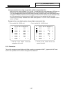
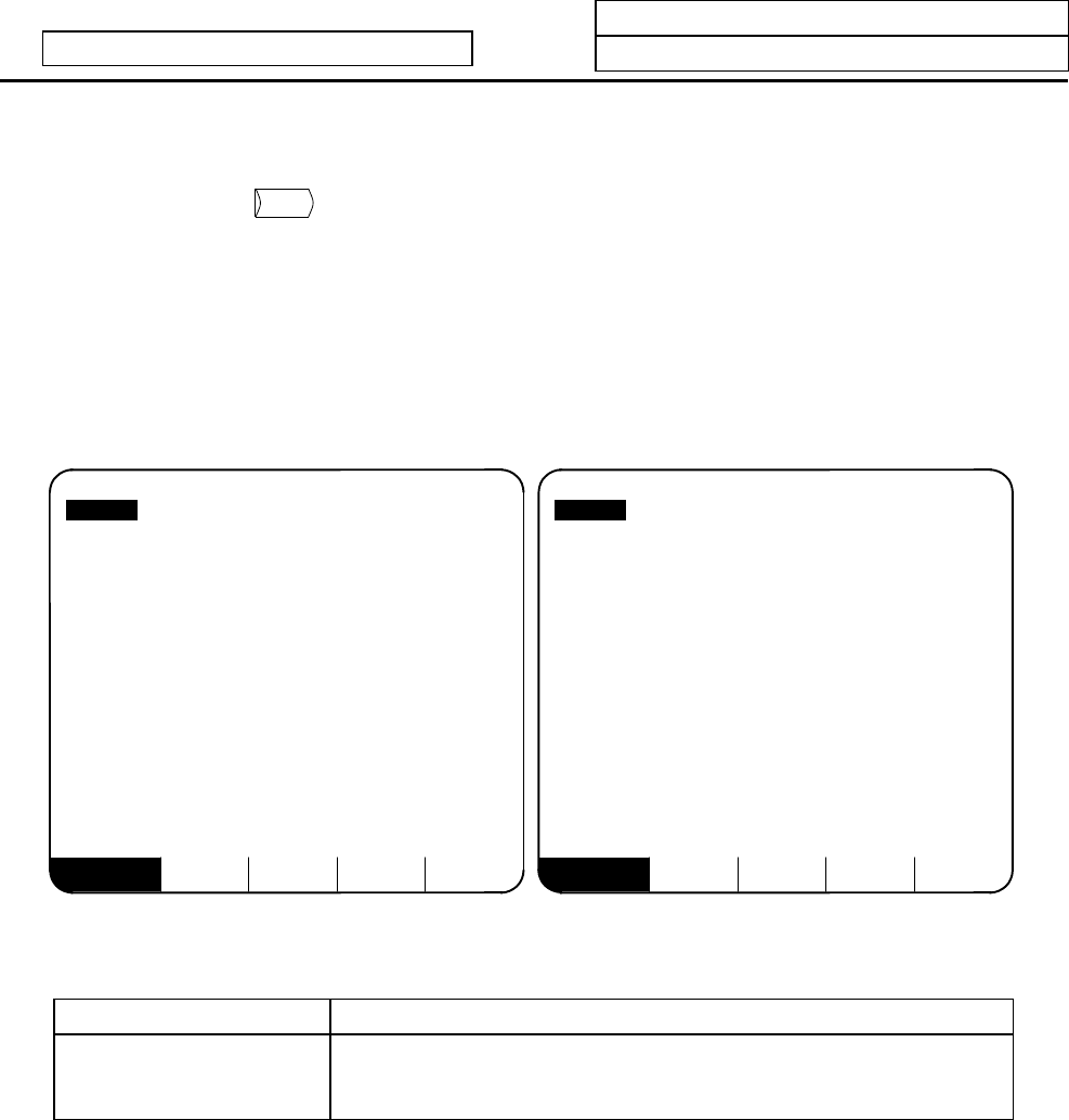
Tool offset memory type I Tool offset memory type II
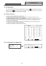
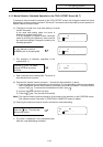
Tool offset data can be set in either absolute or incremental value.
Display item Description
#A: ABS. #I: INC. The valid setting mode, either absolute or incremental mode, is
displayed in reverse video. Before setting data, check that the setting
mode is proper.