


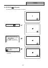


10. Ladder Circuit Monitor
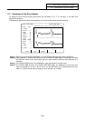
10.1 Parameter Setting
I
-370
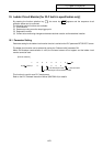
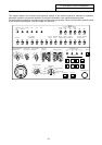
10. Ladder Circuit Monitor [for PLC built-in specification only]
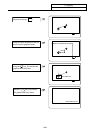
By pressing the function selection key
F0
, the menu key
LADDER
appears and the sequence circuit
operation status can be confirmed.
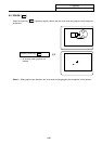
The following monitor functions are available:
(1) Circuit monitor
(2) Screen stop using a monitor stop trigger point
(3) Registration monitor
(4) Current value monitoring changeover between decimal notation and hexadecimal notation
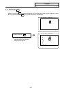
10.1 Parameter Setting
Parameter setting for the ladder circuit monitor function is carried on the PLC parameter BIT SELECT screen.
The ladder circuit monitor can be selected by turning the "Onboard valid" parameter ON.
When GX-Developer communication is valid, the on-board screen will not appear and the ladder circuit
monitor cannot be used.
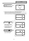
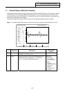
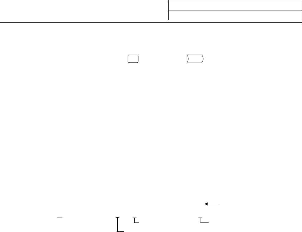
[PLC bit selection]
7 6 5 4 3 2 1 0 Bit
# (6451) Data (0 0 0 1 0 0 0 1)
1: Onboard valid
1: GX Develo
p
er mode
0: GX Developer communication invalid
This function is used for user PLC development.
Refer to the PLC Onboard Instruction Manual (BNP-B2213) for details.