


2. Start up and Adjustment Procedure
2.2 Setting of Various Switches
III-6
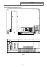
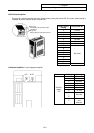
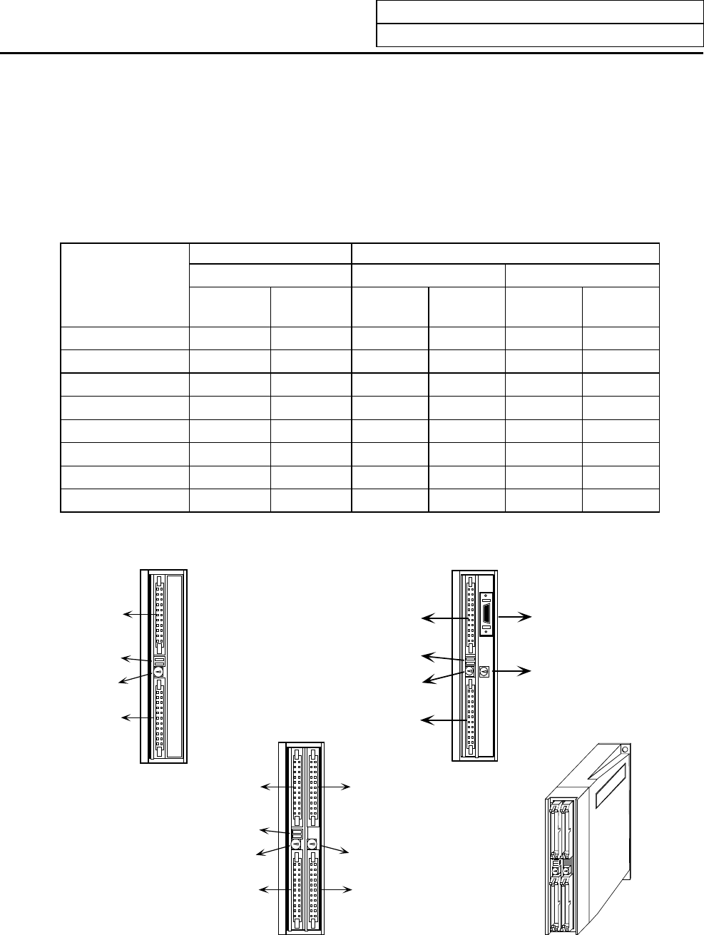
2) Remote I/O unit setting switches
There is a lever-type switch (DS1) and rotary switch (CS1) in the center from of the remote I/O unit.
The DX10 model has one of each switch, and DX11/12/14 has two of each switch.
All DS1 levers must be set and fixed to "OFF: left side". The CS1 setting is "0" to "7", and should be set
while referring to the following table. However, the PCB output (DO) on the right side of
DX11/12/14 looking from the front is a 16-point PCB, so take care.
Make sure that the CS1 setting No., is different from other CS1 setting Nos.
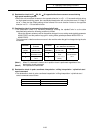
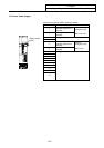
Remote I/O unit CS1 setting
Read in device No. Output device No.
On both units Left side of unit Right side of unit
Rotary switch
CS1 No.
1st
system
2nd
system
1st
system
2nd
system
1st
system
2nd
system
0 X00~X1F I00~I1F Y00~Y1F J00~J1F Y00~Y0F J00~J0F
1 X20~X3F I20~I3F Y20~Y3F J20~J3F Y20~Y2F J20~J2F
2 X40~X5F I40~I5F Y40~Y5F J40~J5F Y40~Y4F J40~J4F
3 X60~X7F I60~I7F Y60~Y7F J60~J7F Y60~Y8F J60~J6F
4 X80~X9F I80~I9F Y80~Y9F J80~J9F Y80~Y8F J80~J8F
5 XA0~XBF IA0~IBF YA0~YBF JA0~JBF YA0~YAF JA0~JAF
6 XC0~XDF IC0~IDF YC0~YDF JC0~JDF YC0~YCF JC0~JCF
7 XE0~XFF IE0~IFF YE0~YFF JE0~JFF YE0~YEF JE0~JEF
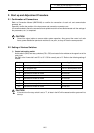
Left input
connector
DIO
specification
switch (DS1)
R
otary
s
witch
(
CS1
)
Left output
connector
DX10
Front view
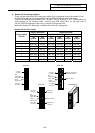
Front view
Left input
connector
DIO
specification
switch (DS1)
Rotary
switch (CS1)
Left output
connector
Left input
connector
DIO
specification
switch (DS1)
Rotary
switch (CS1)
Left output
connector
Front view
Outline drawing
DX11/ DX12
DX14
Right input
connector
Rotary switch
Right output
connector
A
nalog signal input/
output connector
Rotary switch