


4. Absolute Position Detection System
4.3 Starting up Absolute Position Detection System
III-19
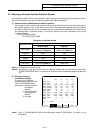
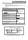
[Operation procedure]
Operation procedure STATE display
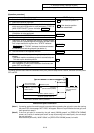
1. Select the "ABS. POSITION SET" screen.
2. Select the handle or jog mode.
3. Ensure that the stopper method is applied for the axis for
which zero-point initialization is to be performed. ("TYPE" of
[ABS. POSITION SET] screen indicates STOPPER
)
• NG
if the absolute position is
lost.
• OK
if the absolute position
has been established.
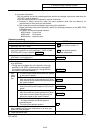
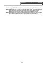
4. Specify "1" to "#0 INIT. SET" for the axis for which zero-point
initialization is to be performed.
5. Specify data for "#2 ZERO".
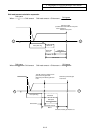
6. Press the axis against the stopper at the machine end.
STOPPER
7. Check that "STATE" indicates that the axis is being pressed.
(After the axis is pressed against the stopper and the current
limit is kept reached for a given time, "STATE" indicates
RELEASE
and "TO END" indicates the distance between
the machine end and the grid point just before it.)
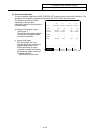
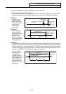
RELEASE
8. The axis moves in the opposite direction. ORIG-RTN
9. The axis automatically stops at the grid point just before the
stopper.
• The basic machine coordinate system is automatically set.
This sets up the absolute position.
10. This completes zero-point initialization.
After completion of zero-point initialization for all axes, turn
power OFF and ON again.
OK
11. Output parameter tape.
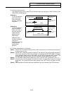
To change just the basic machine coordinate zero point, perform steps 4 and 5 above, and then turn the power
OFF and ON.
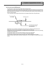
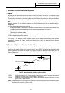
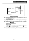
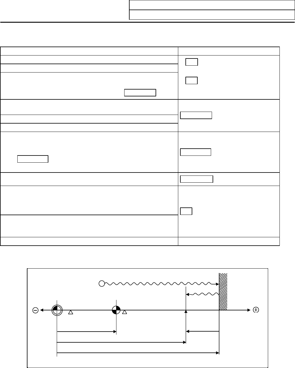
Zero point of basic
machine coordinate
Reference point
Zero-return parameter
"#2037 G53ofs"
Grid point
(Electrical basic position)
"TO END"
Machine end stopper
(Mechanical basic
position)
"#2 ZERO" (#2059 zerbas=1)
"#2 ZERO" (#2059 zerbas=0)
•
Select either "#2 ZERO" with the parameters.
6)
7)
8
)
9)
Manual zero-point initialization
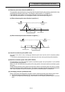
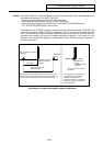
(Note 1) If pressing against the machine end is executed without passing the grip point once after turning
the power ON, the message "NOT PASS" will appear. Return to a point before the last grid, and
then repeat from step 6.
(Note 2) If the first grid point is covered by the grid mask ("#2028 grmask" on [ZERO-RTN PARAM]
screen) as a result of marked point return at step 9 (returning to the basic point), the axis stops
the next grid point.
Note that zero-point shift ("#2027 G28sft" on [ZERO-RTN PARAM] screen) is invalid.