


3. Tool Offset (L system)
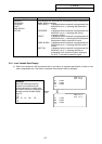
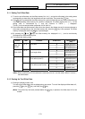
3.2 Tool Length Data
I
-83
Refer to "3 (II). Tool Offset (M system)" for M system.
3.2.1 Manual Tool Length Measurement I
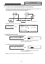
(1) Outline
This function automatically calculates the amount of tool length offset, by moving the tool to the
measurement point with the manual feed. There are two types of measurement methods in manual tool
length measurement I: the basic point method and the measurement value input method. The required
method is selected by setting parameter #1102 tlm.
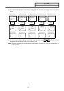
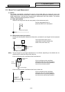
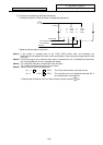
(a) Basic point method
Obtain the tool length with the tool nose placed on the measurement point.
Measurement point
Set the measurement point in
parameter #2015 tlml– beforehand.
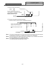
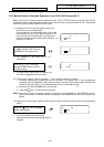
(b) Measurement value input method
Actually cut the workpiece. Measure its dimensions, and obtain the tool length from the measured
values.
Workpiece
Measurement basic point
Measurement
value
The measurement basic point is
characteristic for each machine (the
center of the chuck face, etc.).
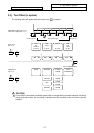
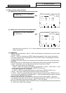
(Note)
The tool length from tool length measurement I is as follows, depending on the whether the 1st
reference point coordinate values have been set.
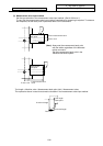
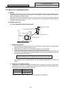
If the 1st reference point coordinate values have been set:
X
-axis
t
ool length
Program basic
position
Z-axis tool length
If the 1st reference point coordinate
values have been set, the tool length is
the distance from the tool's hypothetical
nose to the tool basic position.
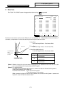
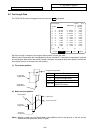
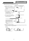
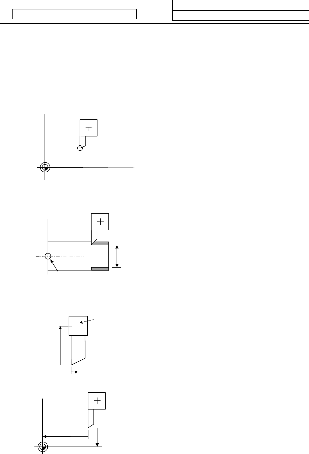
If the 1st reference point coordinate values have not been set:
Z-axis tool
length
X-axis tool length
If the 1st reference point coordinate
values are set to "0", the tool length is
the distance from the tool's hypothetical
tool nose to the machine basic position.