


7. Diagnosis
7.4 PLC Interface Diagnosis
I-288
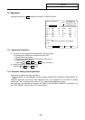
7.4.4 PLC Interface Signal Forcible Definition (Modal Type)
This is PLC interface signal forcible definition of modal type. Once it is set, it is held until canceled.
The device signals that can be set by using this function are X, Y, U, W, S, M, G, F, L, E, T, Q, C, B, D and
R.
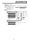
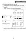
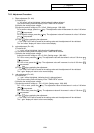
(1) Mode setting
Set the device number to be forcibly defined in DEVICE ( ), definition data in DATA ( ), and 2 in
MODE ( ), then press the
INPUT
key. The data is processed and forcibly defined.
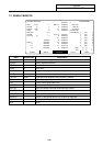
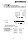
[PLC-I/F] ALARM/DIAGN 4
<SET DATA> X0008=0001
76543210 HEX 76543210 HEX
X0008 ooooo1o1 05 D0005 oooooooo
X0010 oooooooo 00 o11oo1oo
X0018 o1o1oooo 50 D0006 1oooooo1
X0020 1o1ooo11 A3 ooooo1oo
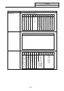
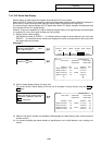
[PLC-I/F] ALARM/DIAGN 4
<SET DATA>
76543210 HEX 76543210 HEX
X0000 oooooooo 00 D0005 oooooooo 00
X0008 ooooo1o1 04 o11oo1oo 64
X0010 oooooooo 00 D0006 1oooooo1 81
X0018 o1o1oooo 50 ooooo1oo 04
DEVICE DATA MODE DEVICE DATA MODE
( X8 ) ( 1 ) ( 2) ( ) ( ) ( )
Press the
INPUT
key.
Set X8 in DEVICE ( ),
1 in DATA ( ), and
1 in MODE ( ).
ALARM SERVO SPINDLE PLC-I/F MENU
X0008 is displayed at the beginning and bit 0 changes to "1".
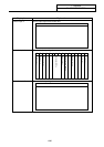
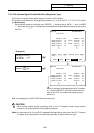
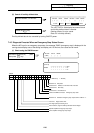
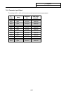
(Example 3)
A
maximum of four sets of forcibl
y
defined device numbers and
numeric data are displayed.
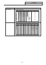
A maximum of four sets can be forcibly defined in mode 2. If four sets have been defined and additional
setting is made, forward feed is made and the subsequent four sets become effective.