


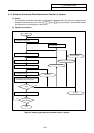
4. Parameters (User)
4.1 Workpiece Coordinate
I-143
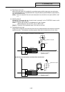
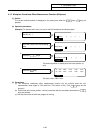
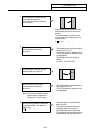
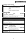
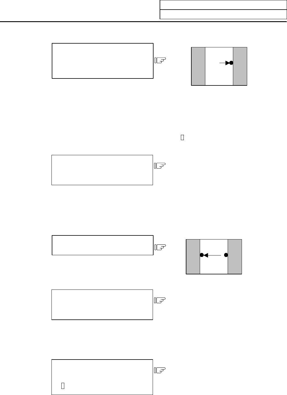
Put the sensor in contact with the
inner walls of the groove.
Only one axis performs contact to
the workpiece.
4)
Automatic re-contact movements are
performed by the axis at the time of
contact.
The measurement coordinate value
of the moved axis is displayed to the
setting column.
#( )( 10.567 )( )( )
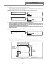
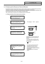
Set the contact position data
(measurement coordinate)
as point A.
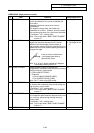
5)
The measurement coordinate value is
set to #1 point A (X, Y).
The setting column is updated to #( 2).
TLM P. A and data of movement axis
are highlighted.
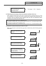
The setting column will change to
blanks.
#1 TLM P. A 10.567 5.678
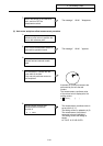
Put the sensor in contact with the
opposite side of the groove.
6)
Point A
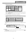
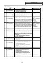
Set the contact position data
(measurement coordinate)
as point B.
7)
The measurement coordinate value is
set to #2 point B (X, Y).
TLM P. B and data of movement axis
are highlighted.
(Note) Hole center workpiece offset
measurement is performed
when point C is set to data.
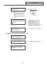
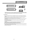
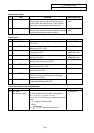
Set the setting number of workpiece
coordinate system, then press the
INPUT key.
#( 54 )( )( )( )
8)
The width center is calculated from
points A and B.
The value that subtracted external
workpiece offset value from the
calculated width center value is set.
The setting column highlight returns to
normal and the value is cleared to 0.