


7. Diagnosis
7.5 Absolute Position Monitor
I-290
7.5 Absolute Position Monitor
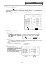
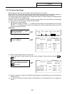
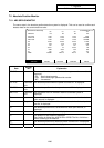
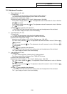
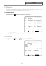
7.5.1 ABS SERVO MONITOR
The servo state in the absolute position detection system is displayed. This can be used to confirm each
detector data for the current machine value.
ABS-SRV ADJUST HISTORY CMPOSIT MENU
[ABS SERVO MONITOR] ALARM/DIAGN 5.1/2
<X> <Y> <Z> <B>
ABS SYS ES ES ES ES
POF POS 0.002 -0.005 -0.005 0.000
PON POS 0.002 -0.008 -0.008 359.998
MAC POS 0.002 -0.008 -0.008 359.998
R0 21202 21202 21202 21202
P0 1379 1379 1379 1379
E0 -331 -331 -331 -331
Rn -32747 24 21503 165
Pn 3388 2550 1192 834
En -331 -331 -331 -331
ABSn 459995 -650015 -20015 -23
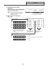
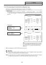
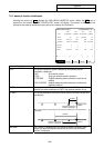
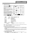
Data
Display
unit
Explanation
ABS SYS The status of the absolute position detection system on the servo side is
displayed.
ES : Semi-closed encoder
ESS : Semi-closed high-speed serial encoder
INC : Incremental
POF POS Command
unit
The absolute position when the power is turned OFF is displayed.
PON POS Command
unit
The absolute position when the power is turned ON is displayed.
MAC POS Command
unit
The coordinate value in the basic machine coordinate system is
displayed.
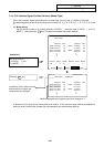
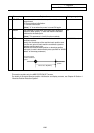
R0 The multi-rotation counter value of the detector, saved when the basic
point was set, is displayed.
P0 Output unit The position in one rotation of the detector, saved when the basic point
was set, is displayed.
E0 The absolute position error, saved when the basic point was set, is
displayed.
Rn The motor accumulated speed is displayed.
Pn The position in one rotation is displayed.
One rotation is divided into 4096, 8192 or 32768. The No. of divisions
differs according to the detector.
En The absolute position error when the power is turned OFF is displayed.
ABSn The current absolute position is displayed.