


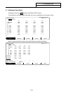
4. Parameters (User)
4.1 Workpiece Coordinate
I-136
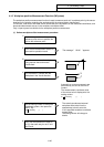
(a) Returning to zero point
After turning the power ON, establish the coordinate system with the dog-type zero point return.
If the absolute position is not established when using the absolute position detection specifications,
carry out initialization first.
(Note) This is not required if the axis to be measured is an axis with no zero point ("#2031 noref"
= 1).
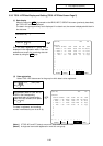
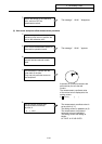
(b) Selecting the tool
Execute the T command with the "manual numeric command" on the "POSITION" screen or with
the MDI operation, select the tool.
(Note 1) Set the offset number of the selected tool in the R register.
(When setting from the user PLC, set as a BCD code.)
(Note 2) Preset the "tool length/wear data" for the tool to be used.
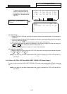
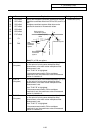
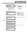
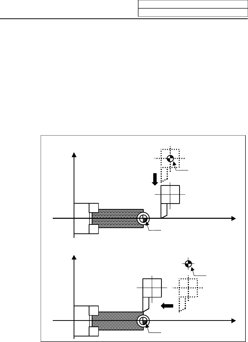
(c) Positioning the tool nose
Using JOG or the handle, move the nose of the axis to be measured above the workpiece coordinate
system zero point. The workpiece coordinate system offset data is measured one axis at a time.
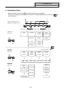
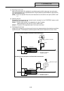
1) 1st axis (X axis) workpiece coordinate offset measurement
Workpiece
Machine zero point
Turret
Workpiece coordinate
system zero point
Z
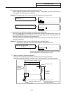
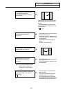
2) 2nd axis (Z axis) workpiece coordinate offset measurement
Workpiece
Machine zero point
Turret
Workpiece coordinate
system zero point
Z
X
X