


2. Monitor
2.6 PLC SWITCH
I-70
2.6 PLC SWITCH
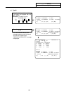
When the menu key
PLC-SW
is pressed, the PLC SWITCH screen is displayed.
The control signals for operation are assigned by using user PLC. The PLC-SWITCH screen enables you to
set each control signal to ON or OFF. (A maximum of 32 signals)
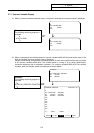
This screen is created with the user PLCs,
so each screen will differ. Refer to the
instruction manual issued by the machine
maker.
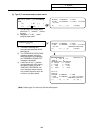
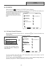
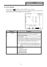
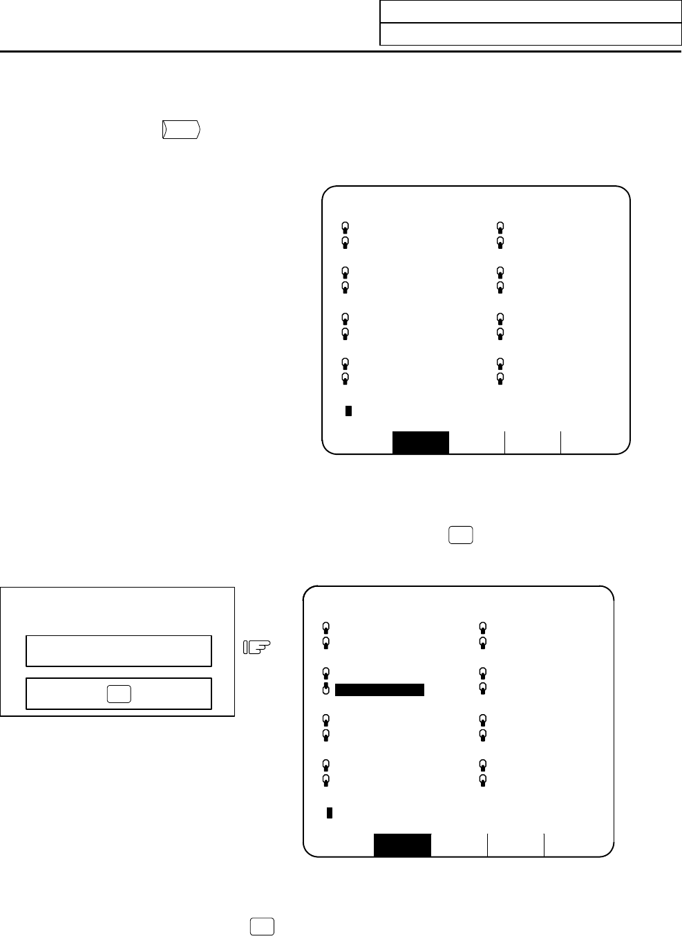
RESERCH PLC-SW COM-VAR LOC-VAR MENU
[PLC SWITCH] PARAM 6. 1/2
#
1 AUTO RESTART 9
2 BLOCK DELETE 10 AUTO POWER OFF
3 MANUAL ABS 11
4 OPTIONAL STOP 12
5 HANDLE IT 13
6 PROGRAM RESTART 14
7 15
8 16
#( )
2.6.1 PLC Switch ON and OFF Operation
Set the number of the switch to be set to ON in # ( ) and press the
INPUT
key. The mark of the switch is set
to the up position.
In this state, the switch function becomes effective and is controlled.
To set OPTIONAL STOP to ON.
Set 4 in # ( ).
Press the
INPUT
key.
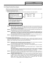
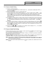
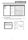
RESERCH PLC-SW COM-VAR LOC-VAR MENU
[PLC SWITCH] PARAM 6. 1/2
#
1 AUTO RESTART 9
2 BLOCK DELETE 10 AUTO POWER OFF
3 MANUAL ABS 11
4 OPTIONAL STOP 12
5 HANDLE IT 13
6 PROGRAM RESTART 14
7 15
8 16
#( )
The switch mark of OPTIONAL STOP is
set to the up position, indicating the
switch ON state.
To set the up-position switch (ON state) to OFF (down-position switch), set the number of the ON-
state switch in # ( ) and press the
INPUT
key.
The PLC switch names (message display) and the function to reverse selected message display are
prepared by using user PLC. These vary depending on the machine maker.