


7. Diagnosis
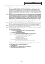
7.2 SERVO MONITOR
I-279
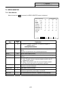
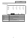
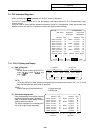
(Note 2) The axis names in this screen are displayed only during the synchronous or independent
operation.
The value of "ERR COMAND", "ERR FB" and "MACHINE" are displayed only during the
synchronous operation. These are all "0.000" during independent or asynchronous operation.
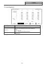
For simple C axis synchronous control, the axis name on the SYNCHRONOUS screen is
displayed only during synchronization. The command error, FB error and machine values
indicate the values only for synchronization. These are all "0.000" during asynchronous
operation.
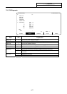
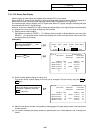
(Note 3) If the FB error exceeds the tolerable value, the operation alarm (51: Synchronization error too large)
will occur, and the motor feed will stop at the point the tolerable value is exceeded. If the
synchronization error too large alarm occurs, refer to the SYNCHRONOUS screen, and move the
axis in the correction mode so that it is positioned within the tolerable range. Note that movement
commands that cause the synchronization error to increase will not move the axis during the
operation alarm (51: Synchronization error too large) so the alarm cannot be reset. The FB error is
also checked during the correction mode, so if the tolerable error range is exceeded during the
correction mode, the operation alarm (51: Synchronization error too large) will occur.
If the synchronization error too large alarm occurs during simple C axis synchronous control,
cancel the synchronization designation (asynchronous), and input reset.
(Note 4) If the FB error is "0" (acceleration/deceleration type or acceleration/deceleration time constant
differ, etc.) during the operation alarm (51: Synchronization error too large), the operation alarm
(51: Synchronization error too large) will be held. This alarm can be canceled by resetting.
(Note 5) The error will not be checked before the first reference point return and when the synchronization
error tolerance value is 0 (synchronization error check invalid).
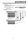
(Note 6) Positions where NC interprets synchronization error as 0 (position used as reference for
synchronization error check)
(a) When zero point is established
(i) For relative position detection or dog type absolute position detection
... 1st reference point
(ii) For dogless absolute position detection
... Basic machine coordinate system zero point (G53 zero point)
(b) When setting operation method after establishing zero point
(i) When operation method is set with first ladders after power ON
... 1st reference point after zero point is established
(during relative position detection)
The current error is held
(during absolute position detection)
(ii) When operation method is set with other method
… Machine position when synchronous control is turned ON
Positions where NC interprets synchronization error as 0 during simple C axis synchronous
control (position used as reference for synchronization error check)
(a) When first zero point is established after power ON
1st reference point
(b) When setting operation method after zero point is established
Machine position at synchronous control ON