11. Visual Analyzer (Waveform display)
11.2 Synchronous Tap Error Display
I
-374
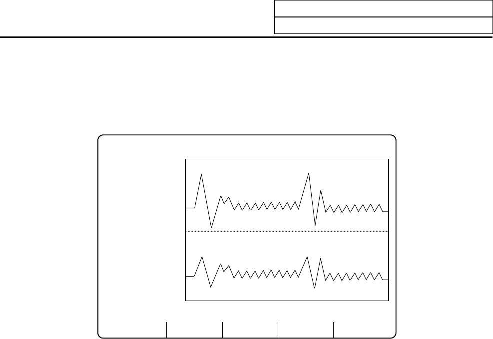
11.2 Synchronous Tap Error Display
To display the error amount during synchronous tap, set either "6" or "7" in "#3 data" or "#7 data" and
display the waveform.
The operation methods and other setting items are the same as the normal waveform display.
SINGLE AUTO DISPLAY
[VISUAL ANALYZER] VISUAL ANALYZER 1.
SYNCH ERR W (mm) 0.006 SYNCH ERR ANG (deg) 2.564
#1 time (1000)
(ms/div) 5
2 CH1 ax ( 1)
3 data (6)
4 range ( 6)
5 level (2)
6 CH2 ax ( 1) 0
7 data (7)
8 range ( 6000)
9 level (-4)
10 type ( )
11 signal ( ) -5
#( )data( )( )
(Note 1)
With the synchronous tap error display, only the waveform during cutting feed is displayed.
(Note 2)
Data displayed in "SYNCH ERR W (mm)" and "SYNCH ERR ANG (deg)" on the screen indicates
the maximum value of the synchronous tap error width obtained from the data displayed as a
waveform.
(Note 3)
The "SYNCH ERR W (mm)" is indicated as a value that allows for the gear ratio.
(Note 4)
The "SYNCH ERR W (mm)" and "SYNCH ERR ANG (deg)" are displayed on the screen only
when the spindle No. is set in "#2 CH1 axis" (or #6 CH2 axis), and 6 (synchronous tap error
width) or 7 (synchronous tap error angle) is set in "#3 data" (or #7 data).


