


7. Diagnosis
7.4 PLC Interface Diagnosis
I-284
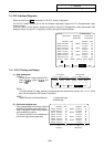
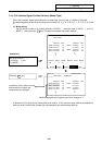
7.4 PLC Interface Diagnosis
When the menu key
PLC-I/F
is pressed, the PLC-I/F screen is displayed.
The PLC-I/F screen enables you to set and display input/output signals for PLC (Programmable Logic
Control) control.
It can be used to check machine sequence operation during PLC development, check input/output data
between control unit and PLC in operation trouble, and make forcible definition.
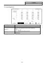
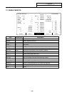
ALARM SERVO SPINDLE PLC-I/F MENU
[PLC-I/F] ALARM/DIAGN 4
<SET DATA> X0008=0001 Y0015=0000
X000A=0001 D0005=0064
76543210 HEX 76543210 HEX
X0000 oooooooo 00 D0005 oooooooo 00
X0008 ooooo1o1 05 o11oo1oo 64
X0010 oooooooo 00 D0006 1oooooo1 81
X0018 o1o1oooo 50 ooooo1oo 04
X0020 1o1ooo11 A3 D0007 o1oooo1o 42
X0028 1ooooo1o 82 1oooo1oo 84
X0030 oooooooo 00 D0008 oooooo1o 02
X0038 oooo11oo 0C 11oooooo C0
DEVICE DATA MODE DEVICE DATA MODE
( ) ( ) ( ) ( ) ( ) ( )
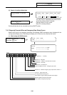
7.4.1 PLC-I/F Setting and Display
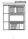
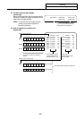
(1) Data setting area
DEVICE ( )
Set the device number used with PLC
(input X
, output Y , and
timer T
).
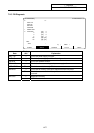
ALARM SERVO SPINDLE PLC-I/F MENU
DEVICE DATA MODE DEVICE DATA MODE
( ) ( ) ( ) ( ) ( ) ( )
For left block For right block
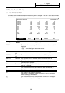
DATA ( )
To forcibly define PLC data, set data corresponding to the setup device number. Set "1" or "0" for bit
data. Set hexadecimal (HEX) data for byte data.
MODE ( )
Specify the type of forcible definition. 1: Single-shot type
2: Modal type
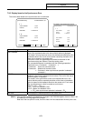
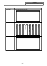
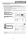
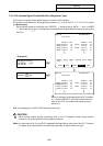
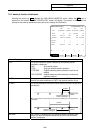
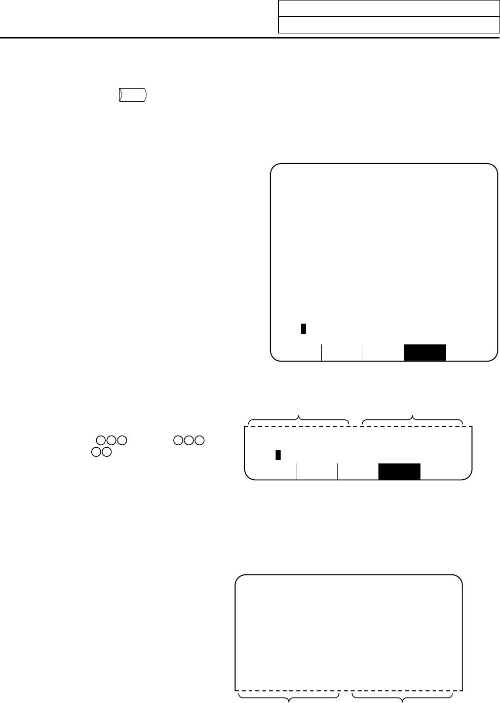
(2) Device data display area
Data corresponding to the device numbers
specified in the setting area is displayed.
Data is displayed in both binary notation
and hexadecimal notation.
The device numbers can be displayed in
the left and right blocks separately.
76543210 HEX 76543210 HEX
X0000 oooooooo 00 D0005 oooooooo 00
X0008 ooooo1o1 05 o11oo1oo 64
X0010 oooooooo 00 D0006 1oooooo1 81
X0018 o1o1oooo 50 ooooo1oo 04
X0020 1o1ooo11 A3 D0007 o1oooo1o 42
X0028 1ooooo1o 82 1oooo1oo 84
X0030 oooooooo 00 D0008 oooooo1o 02
X0038 oooo11oo 0C 11oooooo C0
Left block Right block