


3. Tool Offset (L system)
3.2 Tool Length Data
I-92
Refer to "3 (II). Tool Offset (M system)" for M system.
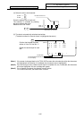
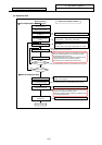
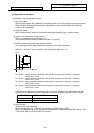
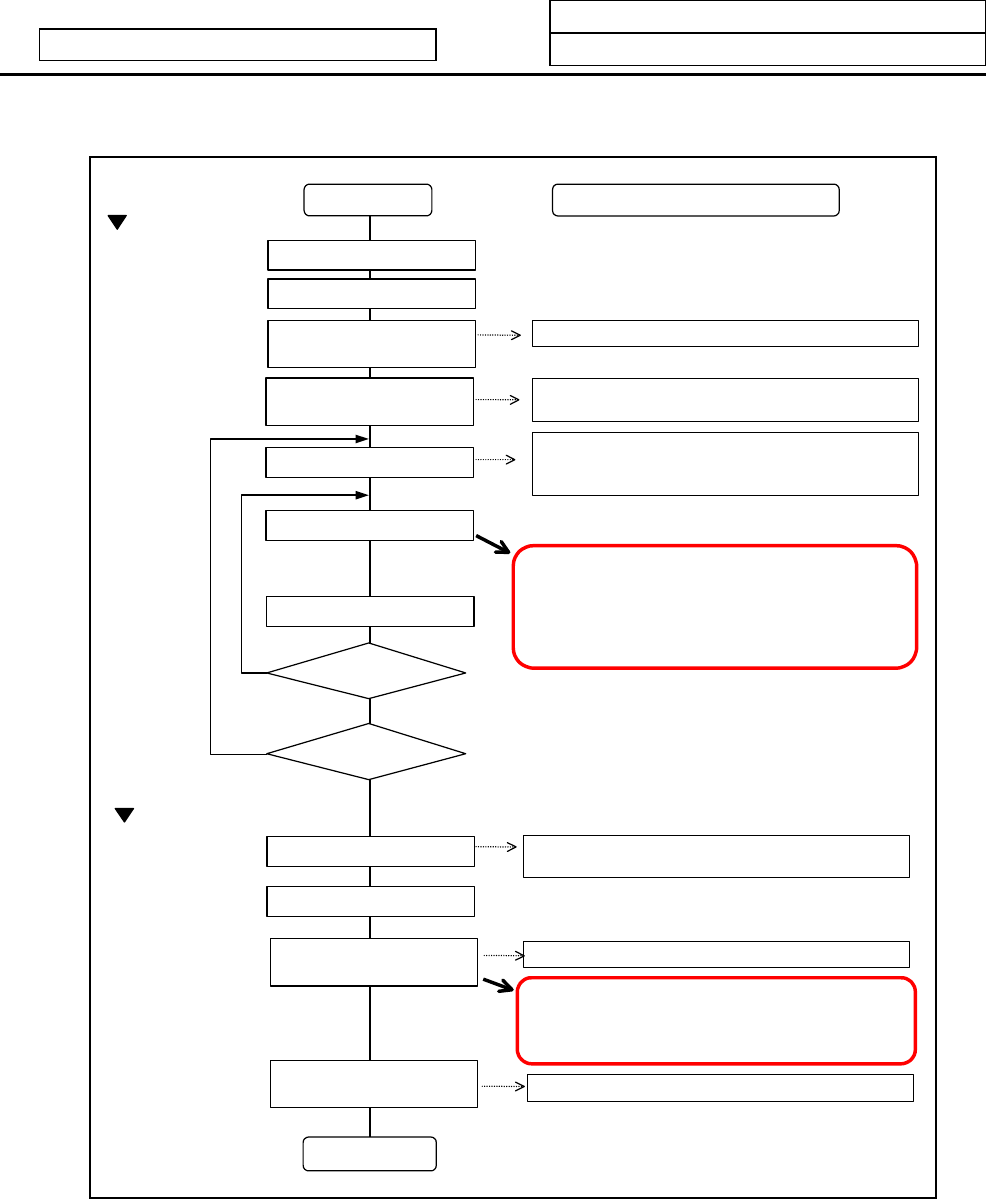
(3) Operation flow
Start of operation
Measure other axes?
Zero point return
End of operation
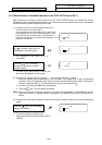
Select manual mode
Turn tool measurement mode
[TLMS] ON
Set No. of tool to be measured
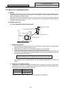
Contact tool against sensor
Retract tool
Set measurement basic
value
Select tool
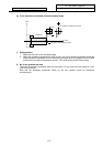
Cut workpiece edges
Input workpiece
measurement signal
Turn tool measurement mode
[TLMS] OFF
Measure other tools?
Yes
No
Yes
No
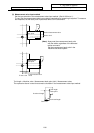
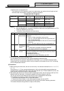
Turn ON Y229 (tool measurement mode).
Preset the following axis specification parameter as the
sensor position. #2015 tlml–, #2016 tlml+
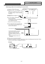
Turn OFF Y229 (tool measurement No.)
Turn ON Y329 (workpiece measurement No.)
Set the compensation No. of the tool to be measured in
the R register.
Tool No.: R2970, Wear data compensation No.: R186
Set the compensation No. of the tool to be used for
cutting in the R register.
The tool length offset amount is automatically calculated
from the contacted position, and is stored in the tool
compensation amount memory.
Tool compensation amount = Machine coordinate value
– Measurement basic value (Sensor position)
The wear amount is cleared after measurement.
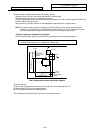
The Z axis workpiece coordinate offset will be measured
and set in the external workpiece offset.
Workpiece coordinate offset = Machine coordinate value
– Tool compensation data
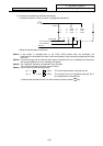
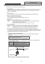
Interface and operation with NC
♦
Do not move the tool in the Z axis direction after cutting.
♦
The axis movement will stop, and can be moved only in
the direction away from the sensor.
External workpiece offset
♦
The tool compensation amount is measured one axis at a time.
Tool compensation amount