


7. Diagnosis
7.4 PLC Interface Diagnosis
I-287
7.4.3 PLC Interface Signal Forcible Definition (Single-shot Type)
This function is used to forcibly define signals to check the PLC functions.
This function is available for the following device numbers: X, Y, U, W, S, M, G, F, L, E, T, Q, C, B, D, and R.
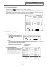
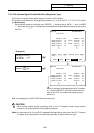
(1) Mode setting
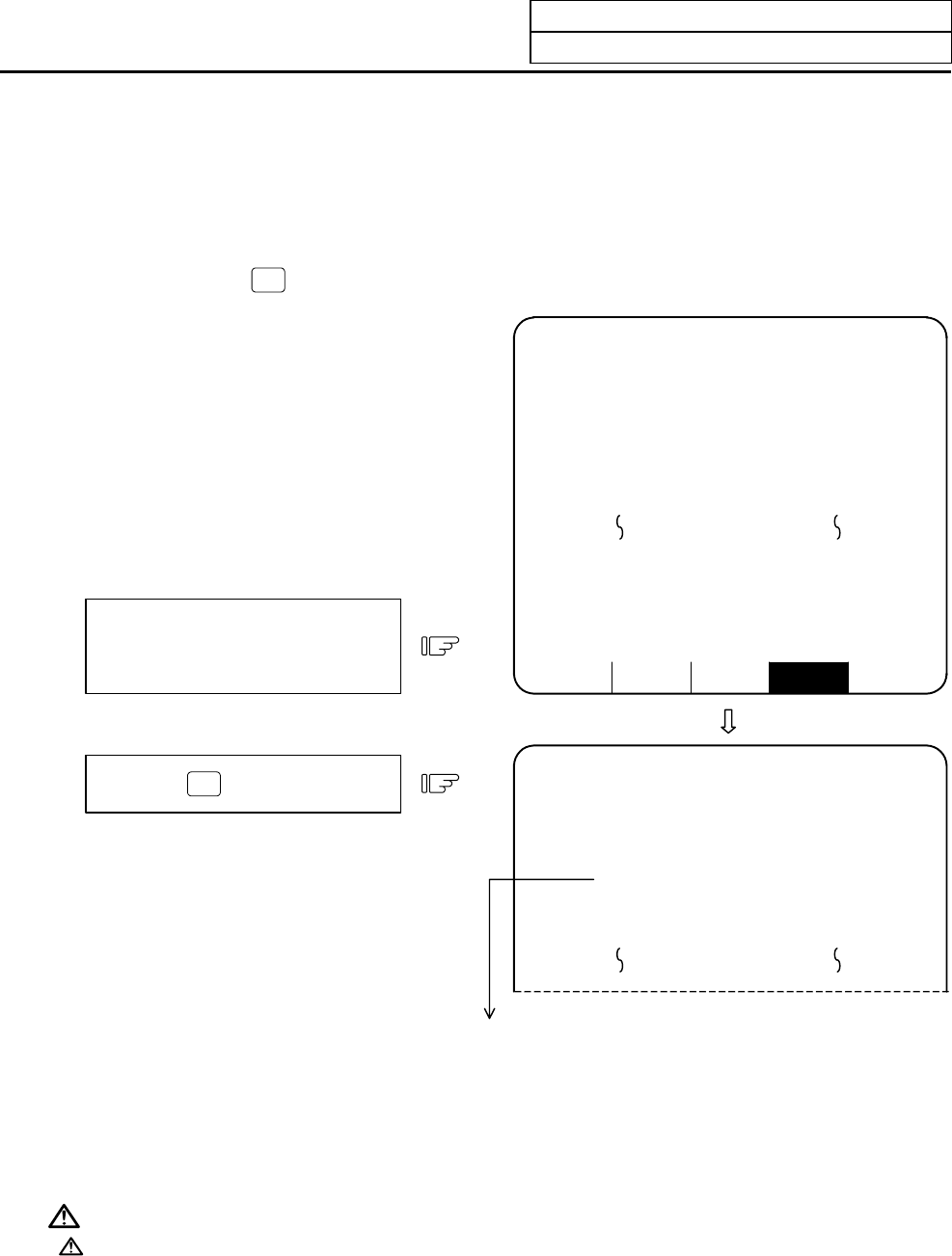
Set the device number to be forcibly set in DEVICE ( ), definition data in DATA ( ), and 1 in
MODE
( ), then press the
INPUT
key. The setup data is processed and forcibly defined at the top of one cycle of
user PLC.
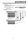
Press the
INPUT
key.
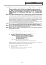
Set M23 in DEVICE ( ),
1 in DATA ( ), and
1 in MODE ( ).
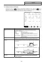
ALARM SERVO SPINDLE PLC-I/F MENU
[PLC-I/F] ALARM/DIAGN 4
<SET DATA>
76543210 HEX 76543210 HEX
M0000 oooooooo 00 D0005 oooooooo 00
M0008 ooooo1o1 05 o11oo1oo 64
M0016 oooooooo 00 D0006 1oooooo1 81
M0024 o1o1oooo 50 ooooo1oo 04
DEVICE DATA MODE DEVICE DATA MODE
( M23 ) ( 1 ) ( 1) ( ) ( ) ( )
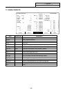
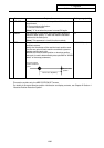
[PLC-I/F] ALARM/DIAGN 4
<SET DATA>
76543210 HEX 76543210 HEX
M0016 oooooooo 80 D0005 oooooooo 00
M0024 ooooo1o1 50 o11oo1oo 64
M0032 oooooooo A3 D0006 1oooooo1 81
M0040 o1o1oooo 82 ooooo1oo 04
M0016 is displayed at the beginning and bit 7 changes
to 1. (If device M23 OUT instruction comes within one
cycle of user PLC, the sequence processing results
will follow.)
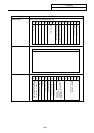
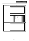
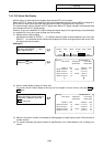
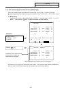
(Example 2)
Data is not displayed in the SET DATA field at the screen top.
CAUTION
When forcibly setting (forcibly outputting) data on the I/F diagnosis screen during machine
operation, pay careful attention to the sequence operation.
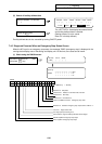
(Note) An input signal (X or U) to the PLC is updated at the beginning of each cycle of the PLC. Therefore,
the signal, once forcibly defined in single-shot type mode, is restored after one cycle.