


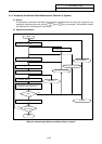
4. Parameters (User)
4.1 Workpiece Coordinate
I-139
4.1.5 Workpiece Coordinate Offset Measurement Function (M System)
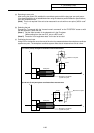
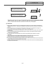
(1) Outline
The current machine position is displayed in the setting area when the
INPUT
SHIFT
keys (
CALC
key) are
pressed.
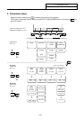
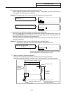
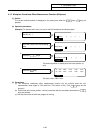
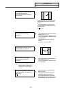
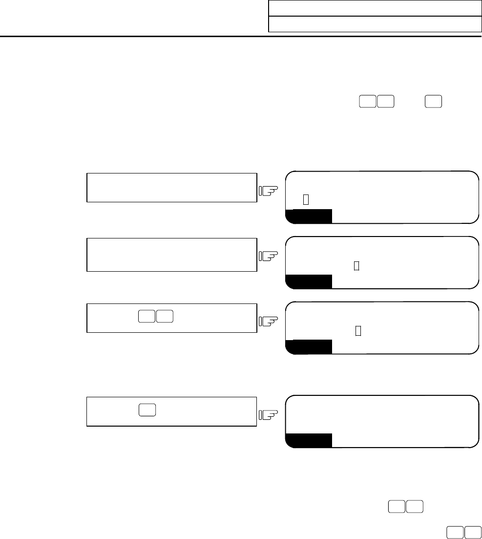
(2) Operation procedures
(Example) To measure the X axis (1st axis) of the G54 workpiece coordinate system.
Set 54 in # ( ).
1)
WORK
#(54) DATA ( ) ( ) ( ) ( )
Move the cursor to the X axis setting
area.
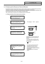
2)
WORK
#(54) DATA ( ) ( ) ( ) ( )
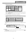
Press the
INPUT
SHIFT
keys.
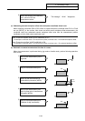
3)
WORK
#(54) DATA ( 3.987)( )( )( )
The machine position is displayed at the cursor position (X
axis).
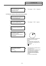
Press the
INPUT
key.
4)
WORK
54 G54 3.987 0.000 0.000 0.000
55 G55 0.000 0.000 0.000 0.000
The data is set in G54 X axis.
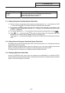
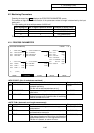
(3) Precautions
(a) The workpiece coordinate offset measurement function will not activate while the tool
measurement mode signal is ON (while the TLM switch is ON.) (The
INPUT
SHIFT
keys will be
ignored.)
(b) If data is set at the cursor position, it will be overwritten with the calculated value when the
INPUT
SHIFT
keys are pressed.
(c) This data cannot be set while the program is running.