


2. Monitor
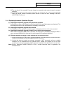
2.2 COORDINATE
I-31
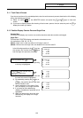
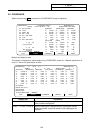
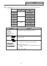
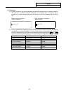
(Note1) The type of position counter to display can be selected with the base specification parameter
(#1137 Cntsel).
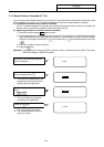
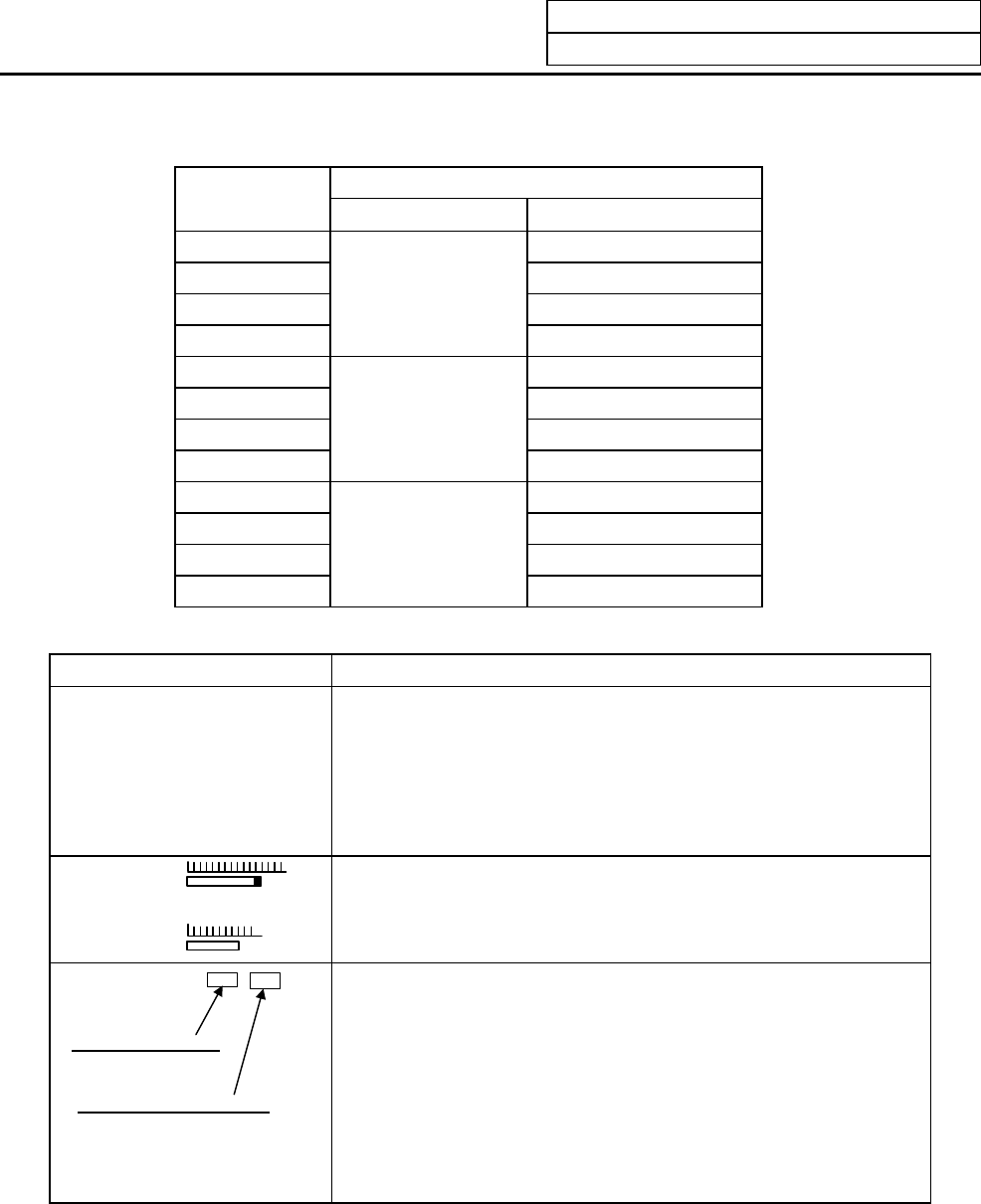
Counter
Parameter
#1137 Cntsel
Left Right
00 or 10 MST
01 or 11 Next command
02 or 12 Current value B
03 or 13
Next command
Manual interrupt amount
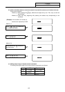
20 MST
21 Next command
22 Current value B
23
Current value B
Manual interrupt amount
30 MST
31 Next command
32 Current value B
33
Manual interrupt
amount
Manual interrupt amount
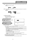
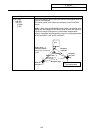
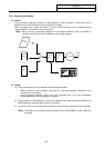
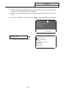
Display item Explanation
N1 G00 X-345.678 Y345.678;
N2 T1234;
N3 S5000 M3;
N4 G00 Z-100;
N5 G01 X100.F500;
N6 Y100.;
N7 G02 X200.R200.;
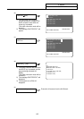
The current work program being executed is displayed.
This is the same as the POSITION screen display.
SPINDLE
Z-AX
The spindle load and Z axis load can be displayed as a bar graph,
using the user PLC.
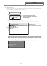
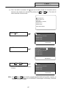
WORK COUNT: /
Workpiece count
Max. workpiece count
Workpiece count :
Indicates count data of the number of workpieces.
Workpiece count Max. value :
The max. workpiece value set in #8003 WRK LIMIT value is
displayed.
Display range: 0~999999