


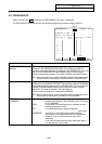
7. Diagnosis
7.1 ALARM MESSAGE
I-271
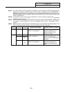
7.1 ALARM MESSAGE
When the menu key
ALARM
is pressed, the ALARM/DIAGN screen is displayed.
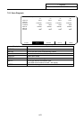
(1) Alarm
The code and number or message relating to an operation alarm, program error, MCP alarm, servo
alarm, or system error are displayed.
(2) Stop code
The automatic operation disable state or stop state in automatic operation mode is displayed in code
and error number.
(3) Alarm message
The alarm messages specified by the
user PLC (built-in) are displayed.
(4) Operator message
The operator messages specified by
the user PLC (built-in) are displayed.
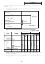
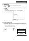
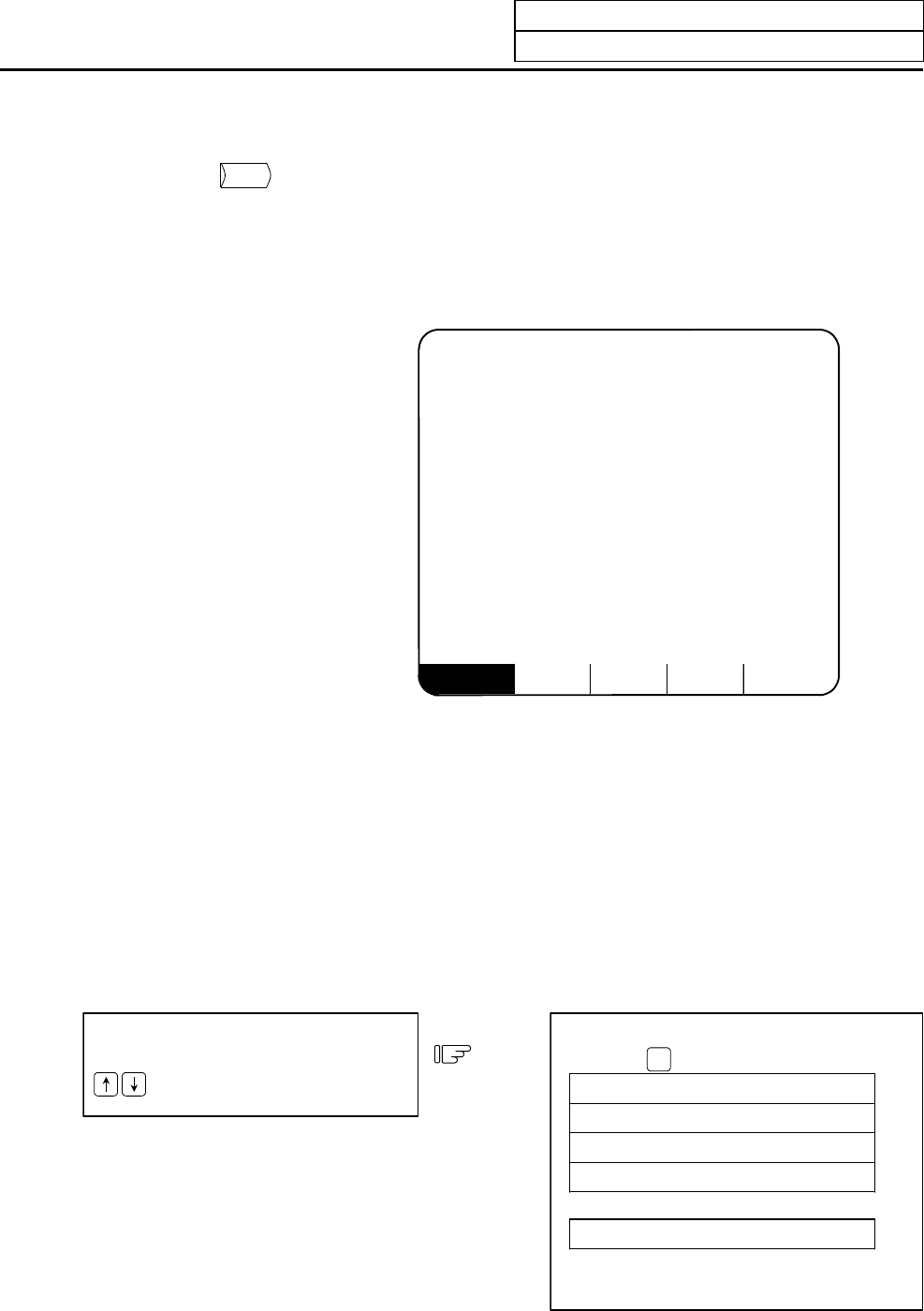
ALARM SERVO SPINDLE PLC-I/F MENU
<ALARM> ALARM/DIAGN 1
M01 OPERATION ERROR 0102
<STOP CODE>
<ALARM MESSAGE>
<OPERATOR MESSAGE>
Refer to the Appendix. List of Alarms for details on the alarms.
When an alarm occurs, the class code will display on all screens.
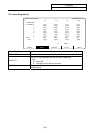
7.1.1 Tracing of Alarm and Stop Codes
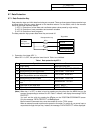
The alarm data will be stored if an alarm occurs. The stop code displayed at automatic operation stop, etc.,
is also stored. The alarm data and stop codes are stored separately. Up to 24 of each is registered, and the
last 24 occurrences can be traced.
(1) Diagnosis of stored alarm and stop code data
The data in which the latest 24 alarms or stop codes are stored can be displayed on the alarm diagnosis
screen and traced. The procedure is shown below.
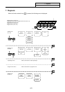
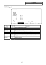
Press either of the following cursor
keys.
The stored alarm data will display.
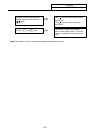
<Alarm>
1
Third to previous
Second to previous
Previous
Latest alarm
<Stop code>
Latest stop code
The digit to the right of the <Alarm> display
shows the occurrence of the data.