1. Setting and Display Unit Operation
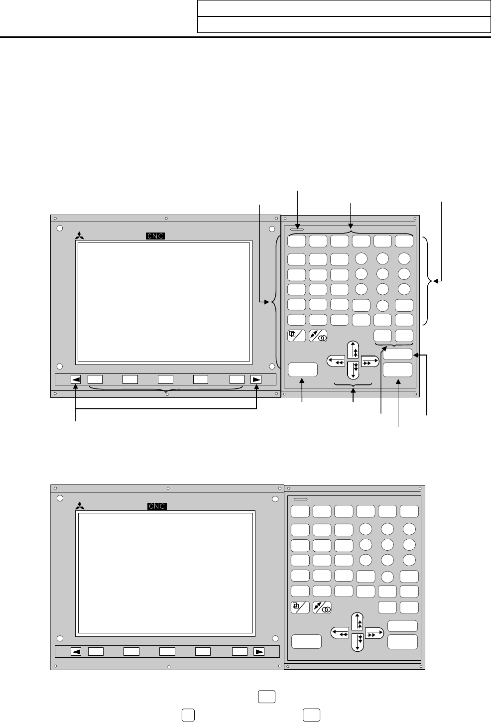
1.1 Appearance of Setting and Display Unit
I-1
1. Setting and Display Unit Operation
1.1 Appearance of Setting and Display Unit
The setting and display unit consists of a display unit (9-inch umber color), keys, and menu keys, as
illustrated below:
(1) Appearance of the CT100 Setting and Display Unit ... Example of key layout for
machining center system
(Separate types FCUA-CR10+KB10 and FCUA-EL10+KB10 are similar.)
MITSUBI SHI
READY
MONI-
TOR
TO OL
PARAM
EDIT
MDI
DIAGN
IN/ OUT
SFG F0
O
A
N
B
G
C
X
U
Y
V
Z
W
F
E
D
L
H
I
P
\
Q
J
R
K
M
(
S
)
T
[
?
78
9
4
56
12
3
0
SP
DELETE
INS
CB
CAN
SHIFT
INP UT
CALC
RESET
-
+
.
,
EOB
]
=
#
/
*
READY LED
A
lphabetic character,
numerical character,
and symbol keys
Setting keys
Function selection keys
CRT/EL display
Page keys
Menu keys
Reset key
Cursor keys
Data correction keys
Input key (calculation)
Shift key
(2)
Appearance of the CT120 Setting and Display Unit ... Example of key layout for lathe
system
MITSUBISHI
READY
MONI-
TOR
TOOL
PARAM
EDIT
MDI
DIAGN
IN/ OUT
SFG F0
O
A
N
B
G
C
X
U
Y
V
Z
W
F
E
D
L
H
I
P
\
Q
J
R
K
M
(
S
)
T
[
?
7
8
9
4
56
1
2
3
0
SP
DELETE
INS
CB
CAN
SHIFT
IN P UT
CALC
RESET
-
+
.
,
EOB
]
=
#
/
*
(Note 1) To enter the letter or symbol on the lower right of an alphabetic or symbol key, press the
corresponding key while holding down the
SHIFT
key.
(Example) Pressing the
O
A
while holding down the
SHIFT
key types letter "A".


