


8. Maintenance Functions
8.2 Data Sampling
III-73
8.2.3 Setting and Display Items
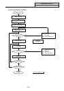
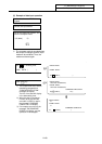
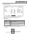
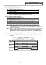
The various data related to sampling of data is set and displayed on the NC-DATA SAMPLING screen.
AUX-PRM AUX-MON SUPPORT MENU
[NC-DATA SAMPLING] ALARM/DIAGN 11.2/2
# 0 SMT START 0 SMT COUNTER 0 <STATE> Sampling stop
<BASIC> <EXTENT>
# 1 CYCLE 1 #11 ADR1 00000300 #21 PROCESS FORM 0
# 2 MARKS 2 #12 ADR2 00010000 #22 E-CONDITION 0
# 3 BUFFER 0 #13 ADR3 00000000 #23 VARIABLE NO. 0
# 4 CAPACITY 2 #14 ADR4 00000000 #24 PLC DEVICE
∗
X0000
# 5 S-CONDITION 0 #15 ADR5 00000000 #25 ADDRESS 00000000
#16 ADR6 00000000 #26 DATA 00000000
#17 ADR7 00000000 #27 DATA MASK 00000000
#18 ADR8 00000000
#( ) ( )
(Note 1) #21 to #27 are extension functions and normally do not need to be set.
(Note 2) The data cannot be set when "#1224 aux08/bit0" is set to "0".
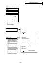
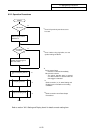
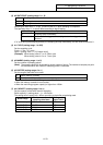
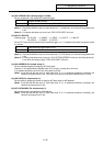
(1) STATE display
The current status is displayed.
Display
Status
"sampling"
Sampling is being executed.
"sampling stop"
Sampling is not being executed, or the sampling process has
completed.
"TRIGGER WAIT"
When #5 is not set to "0" (manual start), this indicates that state
from when #0 was set to "1" to when the sampling start trigger
was detected and sampling was started.
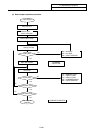
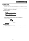
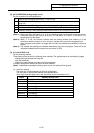
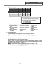
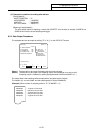
(2) SMT COUNTER (sampling counter)
The position of the sampling buffer during the sampling process is displayed.
When the sampling buffer is valid, the head of the buffer can be seen with the value of the counter at the
end of sampling.
Sampling buffer
0
1
:
n-1 End of buffer (newest data)
Sampling counter (n) →
n Head of buffer (oldest data)
: