3. Tool Offset (L system)
3.2 Tool Length Data
I-90
Refer to "3 (II). Tool Offset (M system)" for M system.
3.2.3 Manual Tool Length Measurement II
(1) Outline
By using a device having a touch sensor, the tool compensation amount can be calculated just by
contacting the tool nose against the touch sensor with manual feed. The calculated results are stored in
the tool compensation amount memory.
After setting the tool compensation amount for each tool, the Z axis external workpiece coordinate
offset data can be set by cutting the edges of the workpiece with manual operation and inputting the
workpiece measurement signal.
(2) Detailed explanation
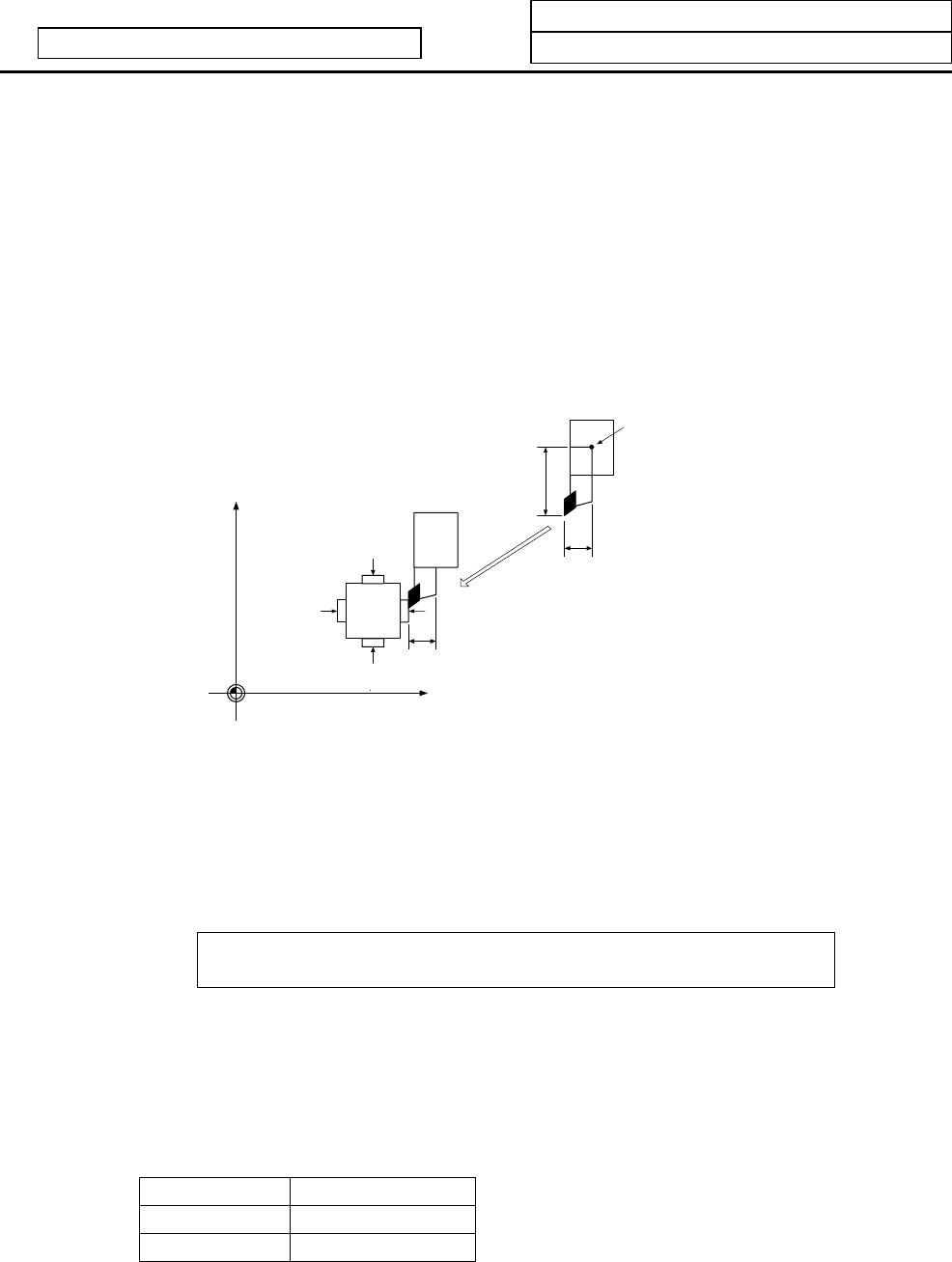
(a) Tool compensation amount measurement
X axis tool compensation amount
Z axis tool compensation amount
X axis − contact surface
X axis + contact surface
Z axis +
contact surface
Z axis − contact surface
Z axis
X axis
Program basic position
1) Measurement method
1. Set the machine coordinate values of the touch sensor's contact surface in the parameters
beforehand as the measurement basic value.
2. Select the tool for which the tool compensation amount is to be measured.
3. Using manual feed, contact the nose of the tool against the touch sensor.
The tool compensation amount will be calculated from the machine coordinate value when the
touch sensor is contacted and the measurement basic value, and will be saved in the memory
as the tool compensation amount.
Tool compensation amount =
Machine coordinate value – measurement basic value (sensor position)
After measuring, the tool wear amounts for the individually designated tool numbers are
cleared.
2) Number of set systems and axes
The system 1 X (1st axis), Z (2nd axis), additional axis, and system 2 X (1st axis), Z (2nd axis),
additional axis can be set. The additional axis is determined with the #1520 Tchg34 additional axis
tool compensation operation selection parameter.
#1520 Tchg34 Additional axis
0 3rd axis selection
1 4th axis selection
Note that the tools in the two systems cannot be measured simultaneously.


