


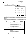
3. Tool Offset (L system)
3.2 Tool Length Data
I-94
Refer to "3 (II). Tool Offset (M system)" for M system.
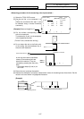
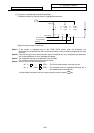
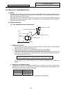
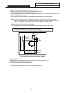
6) Measure tool compensation amount with sensor contact
Approach the tool nose to the sensor with manual or handle feed.
Stop the feed when the tool nose contacts the sensor.
The tool length offset amount will be automatically calculated from the contacted position, and will be
stored in the tool length memory.
After measuring, the wear amount of the designated compensation No. will be cleared.
Note) The sensor contact surface is judged by the NC according to the manual axis movement
direction, so measure the tool compensation amount one axis at a time. The direction of the
axis movement when the sensor contacts the tool will be output to R90 (R290).
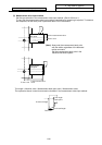
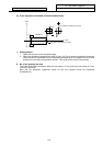
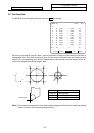
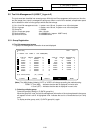
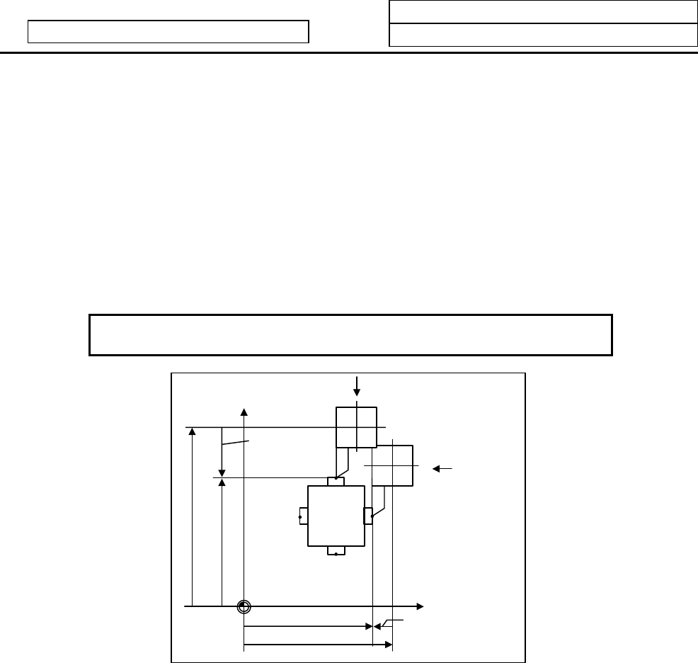
<Details of automatic calculation expression>
The tool compensation amount is automatically calculated with the following expression.
Tool compensation amount
= Machine coordinate value – Measurement basic value
Zaxis
X
axis tool
compensation
amount
X
axis
Turret
Xm
Zm
Z axis tool
compensation
amount
Machine value
Machine value
Turret
Tool compensation amount calculation diagram
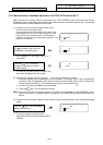
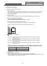
7) Retract the tool.
8) Set the tool compensation amount for the X axis and Z axis using steps 5) to 7).
9) Repeat steps 5) to 8) for the required tools.
10) Turn the tool measurement mode signal OFF.
This completes the measurement of the tool compensation amount.