


7. Diagnosis
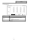
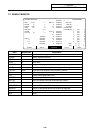
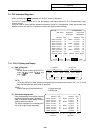
7.3 SPINDLE MONITOR
I-280
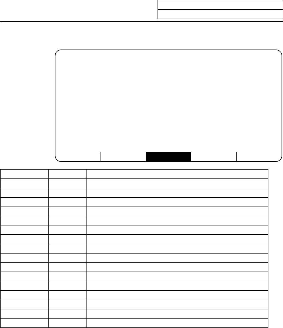
7.3 SPINDLE MONITOR
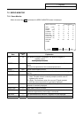
ALARM SERVO SPINDLE PLC-I/F MENU
[SPINDLE MONITOR] ALARM/DIAGN 3.
76543210 #
GAIN (1/sec) 0 CMD 3 L 00000000 UNIT TYP
DROOP (i) 0 H 00000000 UNIT NO
SPEED (rpm) 0 4 L 00000000 S/W VER
LOAD (%) 0 H 00000000 1 WORK TIME
AMP DISP C 5 2 ALARM HIST 1 [00] 0
ALARM STS 1 L 00000001 2 [00] 0
CYC CNT (p) 0 H 00000000 3 [00] 0
2 L 00000000 4 [00] 0
76543210 H 00000000 5 [00] 0
CMD 1 L 00000001 3 L 00000000 6 [00] 0
H 00000000 H 00000000 7 [00] 0
2 L 00000000 4 L 00001010 8 [00] 0
H 00000000 H 00000000 MNT F] F]
/SYS F] F] /F
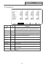
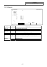
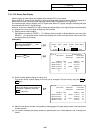
Data Display unit Explanation
GAIN 1/s Spindle position loop gain
DROOP i Position deflection amount
SPEED r/min Motor rotation speed
LOAD % Motor load
AMP DISP 7-segment display of driver
ALARM Alarms other than the amplifier display (max. 3 alarms)
CYC CNT pulse Angle data from detection basic position (Z phase)
CMD Control input signal from control unit
STS Control output signal from driver
UNIT TYP This is the spindle controller type.
UNIT NO This is the spindle controller manufacturing number.
S/W VER This is the spindle controller side software version.
WORK TIME The cumulative ready ON time is displayed.
ALM HIST The No. of the spindle alarm that occurred is displayed.
MNT Maintenance history
/SYS Status