


Appendix 3.
Circular Cutting Radius Error
IV-3
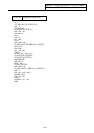
Appendix 3 Circular Cutting Radius Error
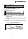
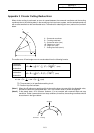
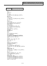
When circular cutting is performed, an error is caused between the command coordinate and the tracking
coordinate due to the tracking delay in the smoothing circuit and servo system, and the workpiece ends up
with a radius smaller than the commanded value. The method for obtaining this error (radius error) is shown
below.
A : Command coordinate
B : Tracking coordinate
R : Command radius (mm)
∆R : Radius error (mm)
∆θ : Angle error (rad)
F : Cutting feed rate (m/min)
A
F
B
∆θ
R
∆
R
F
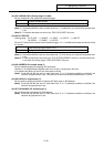
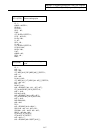
The radius error ∆R and angle error ∆θ are calculated from the following formula.
Exponential
acceleration/
deceleration
∆R = • ( Ts
2
+ Tp
2
) • ( )
2
(mm)
Linear
acceleration/
deceleration
∆R = • ( Ts
2
+ Tp
2
) • ( )
2
(mm)
∆θ= tan
–1
(Ts • ) + tan
–1
(Tp • ) (rad)
TS: Time constant (s) of specified smoothing circuit
TP: Position loop time constant
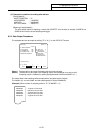
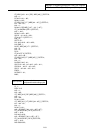
(Note 1) When the ∆R radius error applying with circular cutting does not come within the allowable value,
proceed to reduce the cutting feed rate F, set Ts to a lower value or review the program.
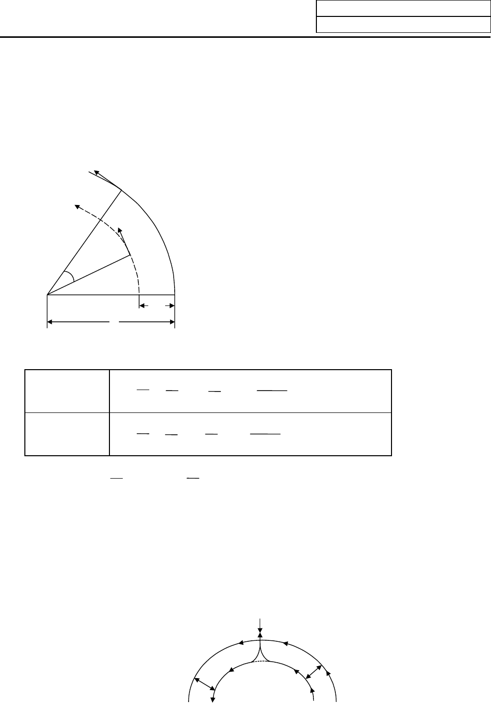
(Note 2) In the steady state, ∆R is constant. However, it is not constant with command start and stop
transitions. Under command start and stop conditions, therefore, the tracking coordinate should
be as shown in the figure below.
Start/stop
Command Tracking
∆R
∆
R
1
2
1
2
1
R
F × 10
3
60
1
24
1
2
1
R
F × 10
3
60
F
R
F
R