


7. Diagnosis
7.5 Absolute Position Monitor
I-291
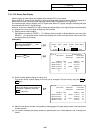
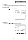
7.5.2 Absolute Position Initialization
Pressing the menu key
ABS-SRV
displays the ABS SERVO MONITOR screen. When the
NEXT
PAGE
key is
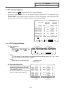
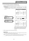
pressed on that screen, the ABS POSITION SET screen will display. This screen is used to set the
parameter data used to establish the zero point and to display the initialization.
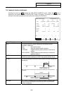
[ABS POSITION SET] ALARM/DIAGN 5. 2/2
<X> <Y> <Z> <C>
TYPE NO-STOPPER STOPPER NO-STOPPER STOPPER
STATE OK NG ORIG-RTN NG
TO END -12345.678 0.000 1.234 0.000
MACHINE -12345.678 NOT PASS 0.000 NOT PASS
#
0 INIT SET 0 1 1 1
1 ORIGIN 0 0 1 0
2 ZERO -12345.678 0.000 1.234 0.000
#( ) ( ) ( ) ( ) ( )
ABS-SRV ADJUST HISTORY CMPOSIT MENU
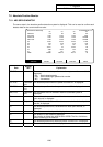
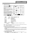
Display item Explanation
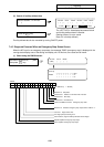
TYPE The position detection system selected by the absolute position
parameter is displayed.
INC. : Incremental system
DOG : Dog type absolute position detection
STOPPER : Dogless absolute position detection machine end
method
NO STOPPER : Dogless absolute position detection marked point
alignment method
STATE The progress of initialization is displayed, such as "OK" if the absolute
position has been established or "NG" if the absolute position is lost.
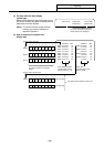
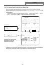
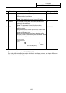
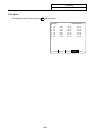
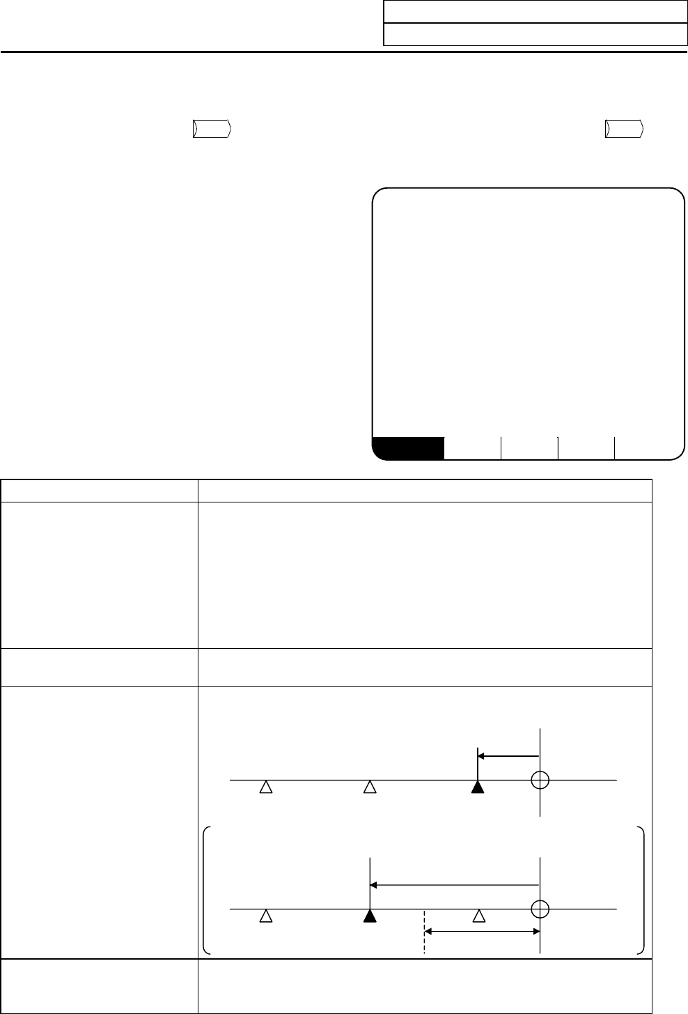
TO END The distance between the machine basic position and the first grid point
is displayed.
TO END
Machine basic
position
Grid point right before
machine end stopper
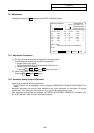
If the first grid point is covered by the grid mask, the distance to the next grid point is
displayed.
TO END
Machine basic
position
Grid mask
Grid point right before
machine end stopper
MACHINE "NOT PASS" is displayed until the machine passes a grid point after
power ON. After the machine passes the grid, the current machine
position is displayed.