


Appendix 7.
Operation Messages on Setting and Display Unit
IV-23
Appendix 7 Operation Messages on Setting and Display Unit
If a setting operation error occurs on any setting and display unit screen, the error No. E
and a message
describing the details of the error will display in the line above the data setting area or the menu display
area.
∆: Message requiring resetting and restarting
×: Message requiring restarting after canceling error conditions.
(The bold characters are the messages displayed on the screen.)
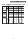
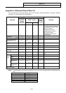
Error No. Error message Details
E01 SETTING ERROR
∆
• The setting data is incorrect. An alphabetic character was set
when only number can be set‚ etc.
• Data was input without setting number (#).
(Word editing)
• Even though no retrieval data was set, menu key [ ↓ ] or [ ↑ ] was
pressed.
• Even though no data is stored in edit buffers, menu key
“Replace” was pressed.
• One of the following characters was entered as the first character
of the retrieval data and edit buffers: 0 to 9, “. ”, “ ” (space), “+”,
“−”, “=”, “*”, “[ ] ”, and “ " " ”.
• When the incremental detection system was used, the parameter
(#0 absolute position setting) was set on the absolute position
setting screen.
• The data input for the standard parameter setting or during
execution of formatting is not “Y” or “N”.
• A value from 4 to 10 was specified for #1043 lang.
• Even though no language data exists, its output and comparison
were attempted. Check the numbers (0253 and 0254) of the
language data to be output.
• When the machine manufacturer macro program memory area is
the SRAM area, the setup parameter #1060 SETUP was set to
“20”.
• When the machine manufacturer macro program memory area is
the SRAM area, writing of the machine manufacturer macro
program was attempted on PROGRAM COPY screen.
E02 DATA OVER
∆
• The setting data exceeded the setting range.
• The compensation data specification exceeded the range when
inputting the tool offset data on tape‚ so that block could not be
input. Press the INPUT key again while the input screen is
displayed‚ and the input will continue from the next block.
• When workpiece coordinate offsets are measured, the
calculation results given by pressing the CALC key are
exceeding the specified range. Correctly specify the tool length
or the wear data of cutting edges used for the calculation.
• #1003 iunit was set to D when the least increment command
0.01µm option was not available.
• When there was no option, 2 or more was specified for #1043
lang. Otherwise, an option was added and 23 or more was
specified for #1043 lang.