


11. Visual Analyzer (Waveform display)
I
-371
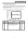
11. Visual Analyzer (Waveform display)
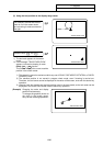
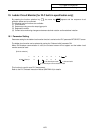
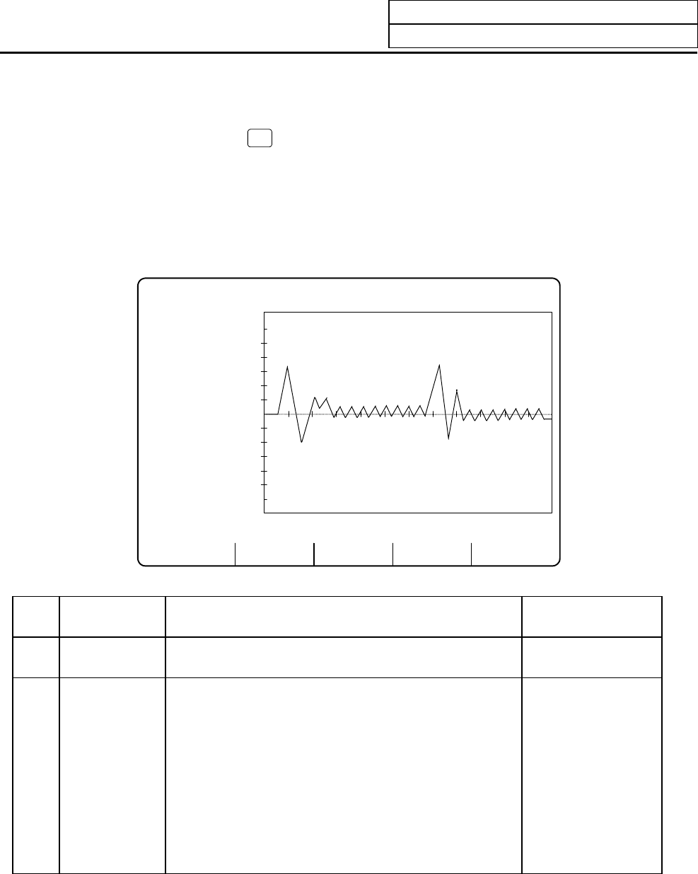
Pressing the function selection key
F0
displays the VISUAL ANALYZER screen. On this screen, changes
in the spindle and servo operation status can be displayed in time units simultaneously for both channels.
During synchronous tap, the difference of the spindle and tap axis position deviation (synchronous error
amount) can be displayed as a waveform.
The waveform data can be output. Refer to section "6.2.6 Outputting Waveform Data" for details.
(Note)
The VISUAL ANALYZER screen is valid when the setup parameter "#1222 aux06/bit2" is set to 1.
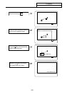
SINGLE AUTO DISPLAY
[VISUAL ANALYZER] VISUAL ANALYZER 1.
#1 time (1000)
(ms/div) 5
2 CH1 ax (X1)
3 data (1)
4 range ( 100)
5 level (0)
6 CH2 ax ( ) 0
7 data ( )
8 range ( )
9 level ( )
10 type ( )
11 signal ( ) -5
#( )data( )( )
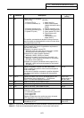
# Parameter Description
Setting range
(units)
1 time (ms/div) Specify the unit of a time axis (horizontal axis)
gradation in milli-second (ms).
1 to 9999
2 CH1 ax Specify the name of the axis to be displayed for CH1.
No waveform data is displayed if ( ) is left blank.
Input "/" to erase the displayed waveform.
Servo axis:
Axis name
[2 characters]
(X1, Y1, Z1, etc.)
Spindle:
S1 to S4
(Just S is sufficient
for the first
spindle.)
"/" will cancel the
axis name.