


7. Diagnosis
7.10 Auxiliary Axis Monitor
I
-304
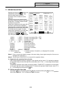
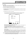
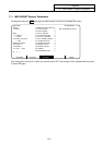
7.10 Auxiliary Axis Monitor
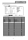
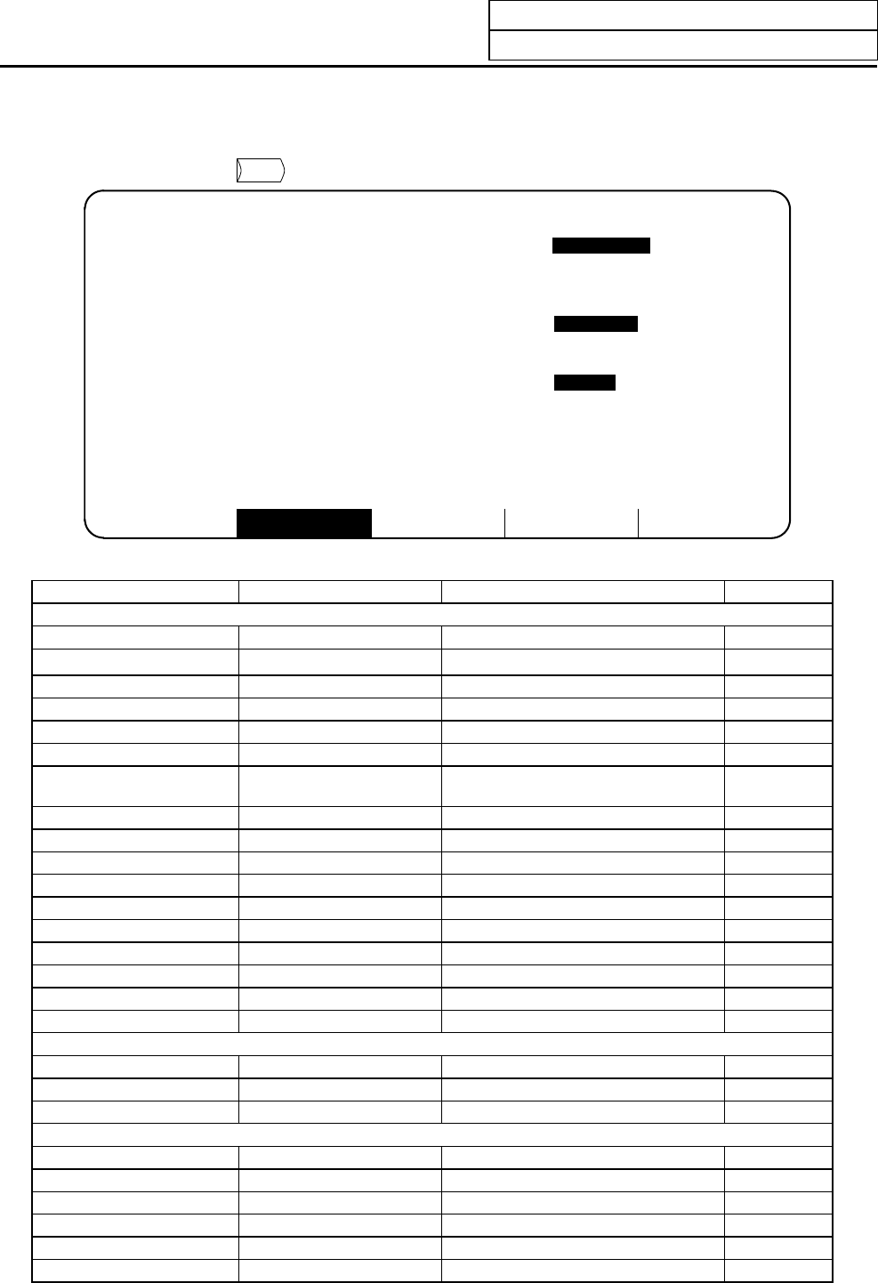
Pressing the menu key
AUX-MON
displays the AUX-MON screen.
AUX-PRM AUX-MON MENU
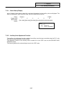
[AUX-MON <1>] AUX1 ALARM/DIAGN 10.1/1
<MON> <COND> <OPE>
DROOP (i) 0 UNIT TYP J2-10CT_ [J]Ope. test mode
SPEED(rpm) 0 S/W num.BND-517W000-C0A [M]Ope. mode JOG
CURRENT (%) 0 Motor HA-FF053__ [P]Paramete set 1
MAX CUR1 (%) 0 [S]Scale
MAX CUR2 (%) 0 <TUNING DATA> [Z]Abs. Pos. init
Motor Load (%) 0 Pos. con. gain 1 0 Initial Origin type
OVER REG (%) 0 Speed con. gain 1 0 Completion
Cur. stn. 0 Pos. con. gain 2 0 [T]Origin set
MAC POS 0.000 Speed con. gain 2 0
Inst. stn. 0 Speed int. comp 0 Normal
Inst. pos. 0.000 Load inertia 0.0
A
UX ALARM aaa 0000 aaa 0000 aaa 0000 aaa 0000
A
LM HIST [S01 0000][S02 0000][S03 0000][S04 0000][S05 0000][S06 0000]
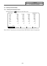
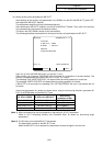
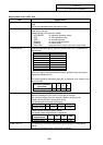
<Auxiliary axis monitor items>
Item Data range MR-J2-CT data name Remarks
MON
DROOP
−
999 to 999
Position droop (i)
SPEED Motor rotation speed 1 (r/min)
CURRENT
−
999 to 999
Effective load rate (%)
MAX CUR1
−
999 to 999
Command torque (%)
MAX CUR2
−
999 to 999
Command torque peak hold (%)
Motor Load
−
999 to 999 Motor load rate
(%)
OVER REG
−
999 to 999
Regeneration resistor heat generation load
rate
(%)
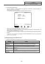
Cur. stn.
1 to 360
J2CT status, station position
MAC POS
−
99999.999 to 99999.999 Feedback machine position
°
Inst. stn.
1 to 360
Target station No.
Inst. pos.
−
99999.999 to 99999.999 Random command position
°
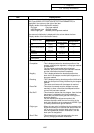
AUX ALARM Alarm No. Alarm information System alarm
Alarm No. Alarm information Servo alarm
Alarm No. Alarm information System warning
Alarm No. Alarm information Servo warning
Alarm No. Alarm information Operation error
ALM HIST [Type Error No.] Alarm history (type and error No.) 6 error max
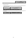
COND
UNIT TYP
S/W num.
Motor
TUNING DATA
Pos. con. gain 1 0 to 999 Position control gain 1 rad/s
Speed con. gain 1 0 to 999 Speed control gain 1 rad/s
Pos. con. gain 2
0 to 999
Position control gain 2 rad/s
Speed con. gain 2
0 to 999
Speed control gain 2 rad/s
Speed int. comp
0 to 999
Speed integral compensation ms
Load inertia
0 to 999.9
Load inertia ratio -fold
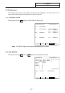
Refer to "7.10.2 Auxiliary Axis Adjustment Function" for details on the <OPE> area on the screen.