


4. Absolute Position Detection System
4.3 Starting up Absolute Position Detection System
III-20
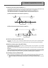
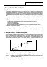
(ii) Automatic initialization
With this method, the axis is pushed against the machine end stopper, and can be used when the
"INIT-SET" mode is selected.
It has the following merits as compared to manual initialization.
1) Pressing is always carried out under the same conditions (feed rate and distance), so
displacements of zero points can be reduced.
2) Part of operation can be automated to ease zero-point initialization.
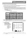
Before performing zero-point initialization, specify the following parameter on the [ABS. POSI
PARAM] screen.
(for details, see Alarm/Parameter Manual):
#2054 clpush : Current limit
#2055 pushf : Push speed
#2056 aproch : Approach point
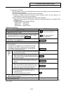
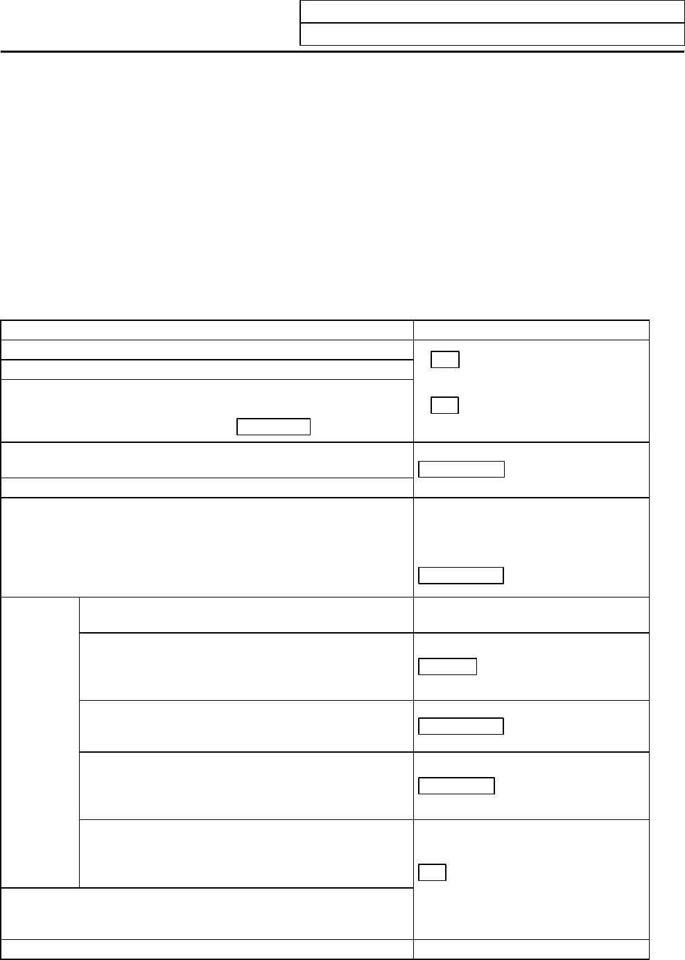
[Operation procedure]
Operation procedure STATE display
1. Select the "ABS. POSITION SET" screen.
2. Select the "INIT-SET" mode.
3. Ensure that the stopper method is applied for the axis for which
zero-point initialization is to be performed. ("TYPE" of [ABS.
POSITION SET] screen indicates STOPPER
)
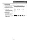
• NG
if the absolute position is
lost.
• OK
if the absolute position
has been established.
4. Specify "1" to "#0 INIT. SET" for the axis for which zero-point
initialization is to be performed.
5. Specify data for "#2 ZERO".
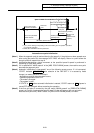
JOG-START
6. Perform jog start for the axis for which zero-point initialization is
to be performed.
• The jog start is available only in the direction of the sign
specified for "#2 ZERO" (toward machine end stopper).
(An attempt to perform the jog start in a wrong direction
encounters "invalid start direction".)
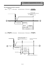
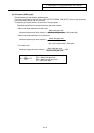
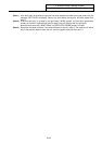
STOPPER 1
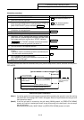
a) The axis moves toward the machine end stopper
at the "press-fit speed".
7. Auto-
matic
opera-
tion
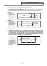
b) The axis hits against the machine end stopper.
After the current limit is kept reached for a given
time, the axis moves toward the approach point at
the "press-fit speed".
ZP-RTN
c) After it reaches the approach point, it again moves
toward the machine end stopper at the "press-fit
speed".
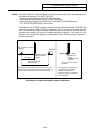
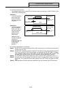
STOPPER 2
d) The axis hits against the machine end stopper.
After the current limit is kept reached for a given
time, the axis moves toward the grid point just
before the stopper at the "press-fit speed".
ORIG-RTN
e) The axis stops at that first grid point.
• The basic machine coordinate system is
automatically set.
This sets up the absolute position.
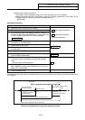
OK
8. This completes zero-point initialization.
After completion of zero-point initialization for all axes, turn
power OFF and ON again.
9. Output parameter tape.
To change just the basic machine coordinate zero point, perform steps 4 and 5 above, and then turn the power
OFF and ON.