


3. Tool Offset (L system)
3.2 Tool Length Data
I-96
Refer to "3 (II). Tool Offset (M system)" for M system.
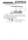
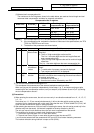
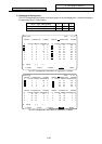
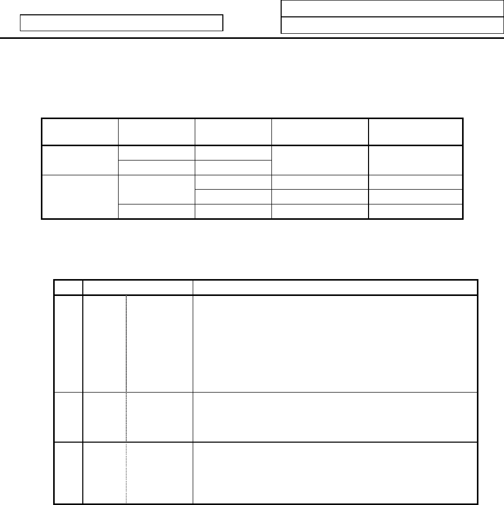
(ii) Selected tool's compensation No.
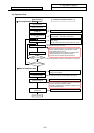
The number set in the R registers, shown in the table below, are used as the tool length and tool
nose wear data compensation numbers for automatic calculation.
Compensation No. R registers
#1098 Tlno. #1130 set_t
#1218 aux02
bit4
Tool length
compensation No.
Tool nose wear
compensation No.
0 0/1
0
1 0/1
R192, R193 R192, R193
0 R36, R37 R192, R193
0
1 R194, R195 R192, R193
1
1 0/1 R194, R195 R192, R193
Notes) 1. If the compensation No. is 0, the compensation amount will be calculated as "0".
2. If the compensation No. exceeds the number of offset sets in the specifications, the "E76
TOOL No. ERROR" error will occur.
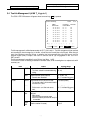
3. The details of the parameters are shown below.
# Items Details
1098
Tlno. Tool length
offset number
Specify the No. of digits in the tool length offset No. in the T
command.
0: The 2 or 3 high-order digits are the tool No.
The 2 or 1 Iow-order digits are the tool length offset and
wear compensation Nos.
1: The 2 or 3 high-order digits are the tool No. and tool length
offset Nos.
The 2 or 1 Iow-order digits are the wear compensation No.
1130
set_t Display
selected tool
number
Specify the tool command value display on the POSITION
screen.
0: T-modal value of program command is displayed.
1: Tool number sent from PLC is displayed.
1218
aux02
(bit4)
Tool number
selection
Specify the R register that contains the tool number used for
automatic calculation when measuring the coordinate offset o
f
an external work piece.
0: Conforms to #1130 set_t.
1: Uses the tool number indicated by user PLC
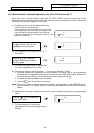
7) Turn the tool measurement mode signal OFF.
This completes the measurement of the external workpiece coordinate offset.
When carrying out this operation independently, follow steps 1) to 7), and when carrying out after
measuring the tool compensation amount, carry out steps 4) to 6) between 9) and 10) of "(a) Setting
the tool compensation amount".
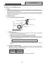
(5) Precautions
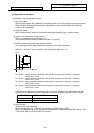
1) When entering the sensor area, the axis can move only in one direction selected from +X, –X, +Z, –Z,
(+Y, –Y).
If two axes (ex. +X, –Z) are moved simultaneously, it will not be clear which contact surface was
contacted, so the measurement will not be made. Note that the error "E78 AX UNMATCH (TLM )" will
occur and the movement will stop for safety purposes.
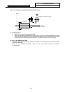
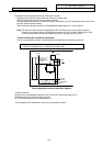
2) After entering the sensor area, if the tool nose is contacting the sensor, the axis can be moved only in the
direction away from the sensor. (An interlock is applied on the entry direction by the NC.)
The axis can move in both directions when the tool nose is separated from the sensor.
The conditions for the axis to move in both directions are as follow:
1. The sensor signal has been OFF for more than 500ms
2. The axis has moved 100µm or more after the sensor signal has turned OFF.
1 and 2 can be selected with the parameter #1227 aux11/bit 2 tool setter chattering measures.
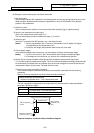
The interlock direction during interlock is output to R91 (R291).