


7. Diagnosis
I-270
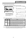
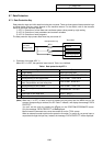
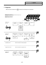
7. Diagnosis
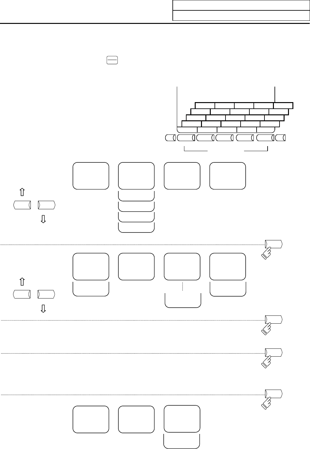
When the function selection key
DIAGN
IN/OUT
is pressed, the following menu is displayed.
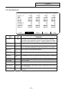
Diagnosis menu (No.9 to 10)
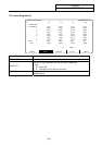
Input/output menu (No.5), Program sever menu (No.1 to 3)
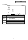
Input/output menu (No.1 to 4)
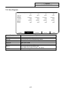
Diagnosis menu (No.5 to 8)
Diagnosis menu (No.1 to 4)
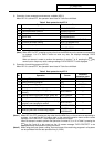
AUX-PRM AUX-MON SUPPORT MENU
COPY HOSTSET HOST IC CARD MENU
INPUT OUTPUT ERASE FILE MENU
ABS-SRV ADJUST HISTORY CONFIG MENU
ALARM SERVO SPINDLE PLC-I/F MENU
Menu selection keys Previous page key Next page key
OPERATION
HISTORY
NC-DATA
SAMPLING
H/W
MONITOR
ABS POSITION
SET
PS DIAGNOSIS
SERVO
DIAGNOSIS-2
SERVO
DIAGNOSIS
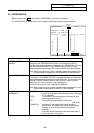
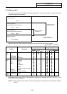
DIAGN menu
No.1 to 4
PREVIOUS
PAGE
NEXT
PAGE
ALARM
MESSAGE
SPINDLE
MONITOR
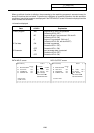
DIAGN menu
No.5 to 8
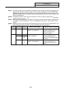
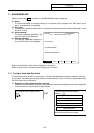
Input/Output menu Refer to the section on data input/output.
Program server menu Refer to the section on program server.
DIAGN menu
No.9 to 10
AUXILIARY
AXIS
PARAMETER
AUXILIARY
AXIS
MONITOR
PLC-I/F
SERVO
MONITOR-2
SERVO
MONITOR
ABS SERVO
MONITOR
OPERATION
HISTORY
S/W
MODULE
TREE
ADJUST
S-ANALOG
PREVIOUS
PAGE
NEXT
PAGE
MENU
MENU
MENU
MENU
MELDASNET
SUPPORT
PARAMETER