


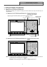

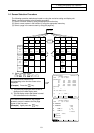
1. Setting and Display Unit Operation
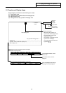
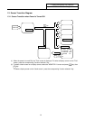
1.2 Functions of Display Areas
I-3
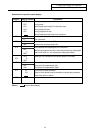
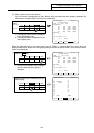
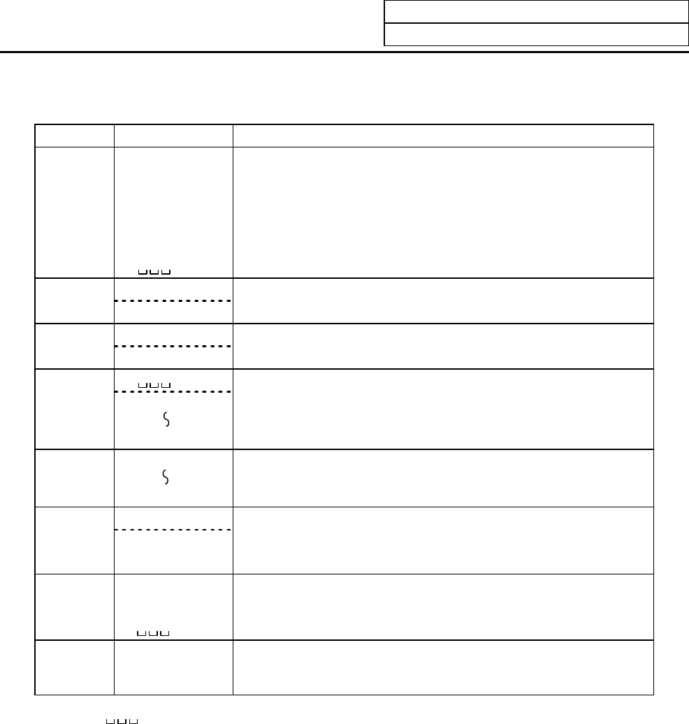
Explanation of operation status display
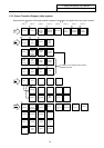
Position Display symbol Explanation
ST1 EMG During emergency stop
RST During reset
LSK When paper tape reader is in label skip state
HLD During feed hold stop
STP During single block stop
Normal operation state other than the above
ST2 mm Metric command
in. Inch command
ST3 ABS Absolute command mode G90
INC Incremental command mode G91
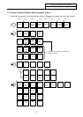
ST4
This indicates that subprogram is not executed.
SB1
SB4
Machining program execution is controlled according to subprogram
data. Each value of 1 to 4 indicates the subprogram depth.
ST5
G54
G59
Selection of the workpiece coordinate system is indicated.
ST6 G40 Tool radius compensation cancel state
G41 During tool R compensation (left)
G42 During tool R compensation (right)
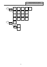
ST7 fix Fixed cycle is being executed.
PR State in which power must be rebooted to validate set parameter.
State other than the above.
ST8
(Note 1)
denotes blank display.