


2. Start up and Adjustment Procedure
2.1 Confirmation of Connections
III-5
2. Start up and Adjustment Procedure
2.1 Confirmation of Connections
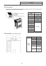
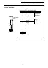
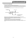
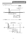
Refer to Connection Manual (BNP-B2183) to confirm the connection of each unit and communication
terminals, etc.
Especially confirm the position of the input power and connection connectors, etc.
It is recommended to leave the servomotor and spindle motor drive lines disconnected until the settings of
the parameters, etc., is completed.
CAUTION
Ground the signal cables to ensure stable system operation. Also ground the control unit main
frame, power distribution panel and machine to one point, so they all have the same potential.
2.2 Setting of Various Switches
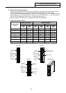
1) Control unit setting switch
A slide switch (SW1) and rotary switches (CS1, CS2) are located in the window on the upper front of the
control unit.
Set SW1 to the "lower side" and CS1 to "0". CS2 is normally set to "0". Refer to the following settings if
needed.
Switch Operation Application
0 Normal operation mode Normal operation
1 PLC program stop For PLC development work
2 Not used
3 Maintenance mode for maker Do not use.
4 Not used
5 Maintenance mode for maker Do not use.
6 Not used
7 The entire memory will be erased, so do not set this. Do not use.
8~F Maintenance mode for maker Do not use.
CAUTION
If the control unit's rotary switch is set to "7", all data in the NC will be erased and the system will not
start up.