


Appendix 2.
Table of Command Value Ranges
IV-2
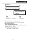
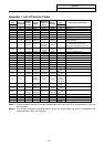
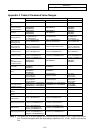
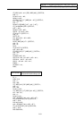
Appendix 2 Table of Command Value Ranges
Linear axis Rotary axis
Input unit (mm) Input unit (inch) Input unit (°)
Minimum input setting
unit
0.001/0.0001/0.00001 0.0001/0.00001 0.001/0.0001/0.00001
Maximum stroke
(value for machine
coordinate system)
±99999.999mm
±9999.9999mm
±999.99999mm
±9999.9999inch
±999.99999inch
±99999.999°
±9999.9999°
±999.99999°
Maximum programmable
dimension
±99999.999mm
±9999.9999mm
±999.99999mm
±9999.9999inch
±999.99999inch
±99999.999°
±9999.9999°
±999.99999°
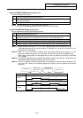
Rapid traverse rate
(including dry run)
1 to 1000000mm/min
1 to 100000mm/min
1 to 10000mm/min
1 to 39370inch/min
1 to 3937inch/min
1 to 1000000°/min
1 to 100000°/min
1 to 10000°/min
M system
Cutting feed rate
(including dry run)
0.01 to 1000000mm/min
0.001 to 100000mm/min
–
0.001 to 100000inch/min
0.0001 to 10000inch/min
0.01 to 1000000°/min
0.001 to 100000°/min
–
L system
Cutting feed rate
(including dry run)
0.001 to 1000000mm/min
0.0001 to 100000mm/min
0.00001 to 10000mm/min
0.0001 to 39370.0787inch/min
0.00001 to 3937.00787inch/min
0.001 to 1000000°/min
0.0001 to 100000°/min
0.00001 to 10000°/min
M system
Synchronous feed
0.001 to 999.999mm/rev
0.0001 to 99.9999mm/rev
–
0.0001 to 999.9999inch/rev
0.00001 to 99.99999inch/rev
0.01 to 999.99°/rev
0.001 to 99.999°/rev
–
L system
Synchronous feed
0.0001 to 999.9999mm/rev
0.00001 to 99.99999mm/rev
0.000001 to 9.999999mm/rev
0.000001 to 99.999999inch/rev
0.0000001 to 9.9999999inch/rev
0.0001 to 999.9999°/rev
0.00001 to 99.99999°/rev
0.000001 to 9.999999°/rev
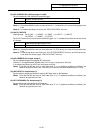
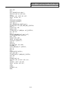
2nd to 4th reference point
offset
(value with machine
coordinate system)
±99999.999mm
±9999.9999mm
±999.99999mm
±9999.9999inch
±999.99999inch
±99999.999°
±9999.9999°
±999.99999°
Tool offset amount
(tool length)
±999.999mm
±99.9999mm
±9.99999mm
±99.9999inch
±9.99999inch
Tool offset amount
(wear)
±9999.999mm
±999.9999mm
±99.99999mm
±9.9999inch
±0.99999inch
Incremental feed amount
0.001mm/pulse
0.0001mm/pulse
0.00001mm/pulse
0.0001inch/pulse
0.00001inch/pulse
0.001°/pulse
0.0001°/pulse
0.00001°/pulse
Handle feed amount
0.001mm/pulse
0.0001mm/pulse
0.00001mm/pulse
0.0001inch/pulse
0.00001inch/pulse
0.001°/pulse
0.0001°/pulse
0.00001°/pulse
Soft limit range
(value with machine
coordinate system)
–99999.999mm to +99999.999mm
–9999.9999mm to +9999.9999mm
–999.99999mm to +999.99999mm
–9999.9999inch to +9999.9999inch
–999.99999inch to +999.99999inch
1 to 359.999°
1 to 359.9999°
1 to 359.99999°
Dwell time
0 to 99999.999s 0 to 99999.999s
Backlash compensation
amount
0 to ±9999pulse 0 to ±9999pulse 0 to ±9999pulse
Pitch error compensation
amount
0 to ±9999pulse 0 to ±9999pulse 0 to ±9999pulse
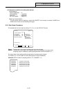
M system
Thread lead (F)
0.001 to 999.999mm/rev
0.0001 to 99.9999mm/rev
–
0.0001 to 99.9999inch/rev
0.00001 to 9.99999inch/rev
M system
Thread lead (precision E)
0.00001 to 999.99999mm/rev
0.000001 to 99.999999mm/rev
–
0.000001 to 39.370078inch/rev
0.000001 to 3.937007inch/rev
L system
Thread lead (F)
0.0001 to 999.9999mm/rev
0.00001 to 99.99999mm/rev
0.000001 to 9.999999mm/rev
0.000001 to 99.999999inch/rev
0.0000001 to 9.9999999inch/rev
L system
Thread lead (precision E)
0.00001 to 999.99999mm/rev
0.000001 to 99.999999mm/rev
0.0000001 to 99.9999999mm/rev
0.000010 to 9.9999999inch/rev
0.0000010 to 0.99999999inch/rev
(Note 1) The second line in the table applies when the least setting increment is 0.001, 0.0001 from the first
line. The third line applies when the least setting increment is 0.001, 0.0001, 0.00001 from the first
line.