


4. Parameters (User)
4.1 Workpiece Coordinate
I-141
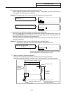
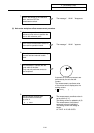
Return the sensor to the reference
point, and turn OFF the
measurement switch.
7)
The message " WLM " disappears.
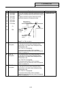
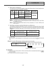
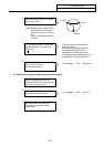
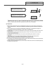
(2) Hole center workpiece offset measurement procedure
Perform an operation such as a
reference point return to position the
tool on the reference
p
oint.
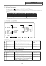
1)
Turn ON the measurement switch on
the machine operation board.
2)
The message " WLM " appears.
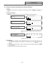
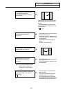
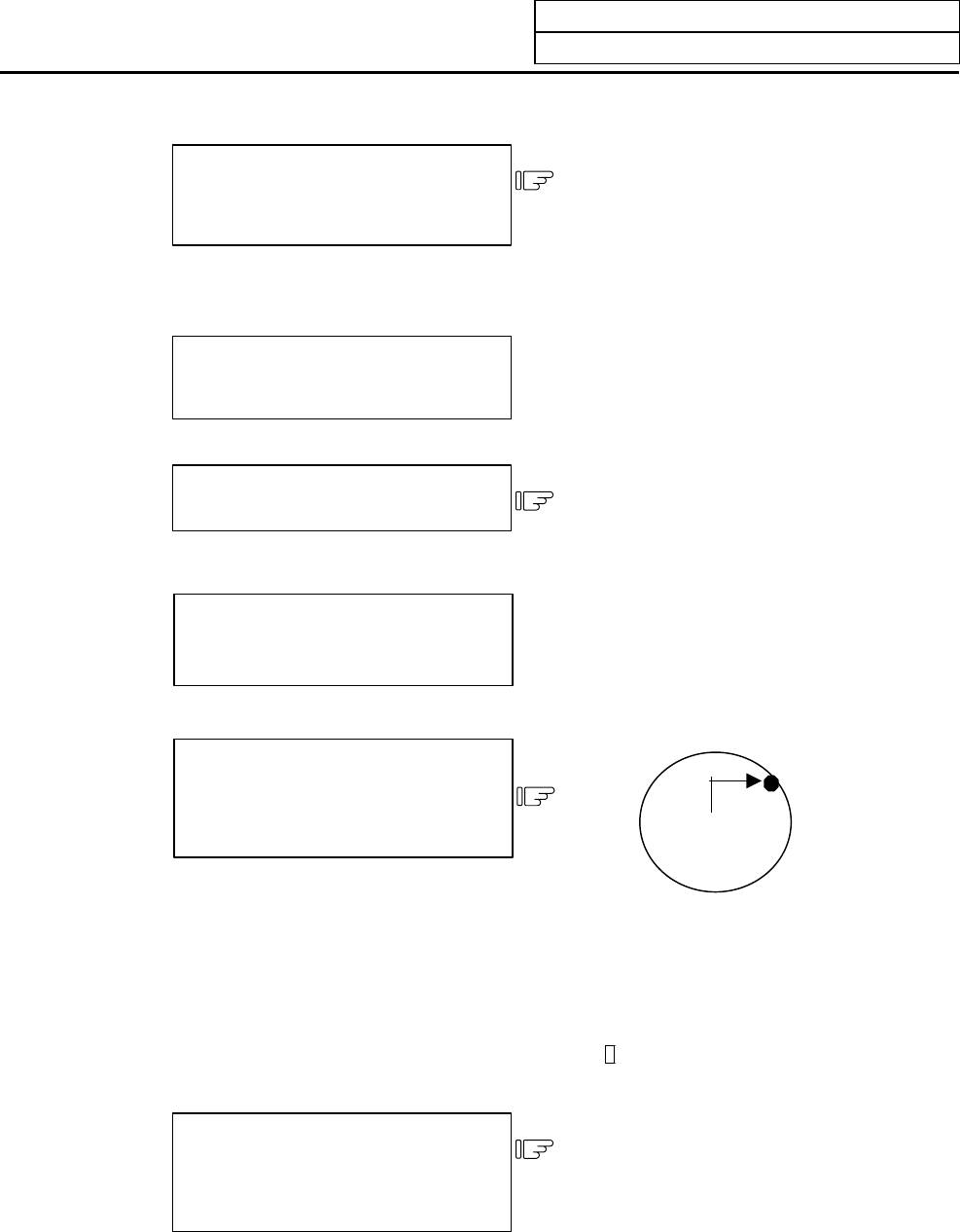
Move the sensor into the hole using
manual feed and manual handle
feed.
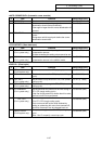
3)
Put the sensor in contact with the
inner walls of the hole.
Only one axis performs contact to
the workpiece.
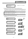
4)
Automatic re-contact movements are
performed by the axis that did
contact.
The measurement coordinate value
of the moved axis is displayed to the
setting column.
#( )( 123.45 )( )( )
Set the contact position data
(measurement coordinate)
as point A.
#( 1) INPUT
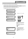
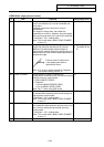
5)
The measurement coordinate value is
set to point A (X, Y).
The setting column is updated to #( 2).
The measurement A and data of
movement axis are highlighted.
The setting column will change to
blanks.
#1 TLM P. A 12.345 45.678