


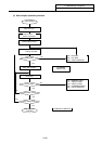


8. Maintenance Functions
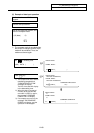
8.2 Data Sampling
III-76
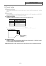
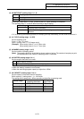
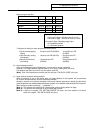
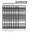
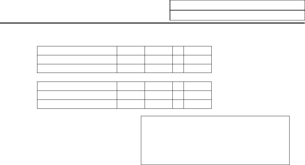
Setting range (index No.)
Servo axis 1st axis 2nd axis ... 14th axis
Feedback position 000100 000200 ... 000E00
Command position 000101 000201 ... 000E01
Spindle 1st axis 2nd axis ... 4th axis
Feedback position 010000 020000 ... 040000
Command position 010001 020001 ... 040001
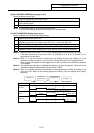
High-order 4 digits: Axis index
High-order 2 digits : Spindle index (01 to 04)
Low-order 2 digits : Servo axis index (01 to 0E)
Low-order 2 digits: Sampling target index
00: Feedback position
01: Command position
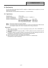
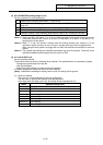
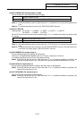
* Examples of setting for each purpose are shown below.
• Synchronized tapping
setting
: 3rd servo axis FB (000300) - 1st spindle axis FB
(010000)
• High-accuracy setting
(roundness)
: 1st servo axis FB (000100) - 2nd servo axis FB
(000200)
• Spindle synchroniza-
tion setting
: 1st spindle axis FB
(010000)
- 2nd spindle axis FB
(020000)
(b) Actual address method
If the actual address is known beforehand, it can be set by directly inputting it.
However, if an illegal address (highest-order bit 0) is input, a setting error will occur.
If an address that does not exist is set, the system could fail.
(Note) Even if the data does not match near the 4th byte, "E02 DATA OVER" will occur.
(c) Head address automatic setting method
When the symbol is set in the setting area, the head address of that symbol will be searched
for, and will be automatically set as the sampling address.
Normally, the data to be actually sampled is the actual address obtained by adding the data offset
(relative address from address determined with symbol) to the address determined with this method.
When setting a symbol containing "_", substitute "=".
(Note 1) The symbols are limited to NC internal table symbols having within 16 digits.
(Note 2) The symbols are searched for as all lowercase symbols.
(Note 3) If there is no symbol, "E01 SETTING ERROR" will occur, and if the symbol is not found
within the 4 bytes, "E02 DATA OVER" will occur.