


3. Adjustment of Dog-type Reference Point Return
3.2 Dog-type Reference Point Return
III-9
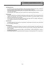
(2) Reference point
The reference point is the point positioned to when the dog-type reference point return is executed.
Note that a separate setting method is used for the absolute position detection.
The reference point is the point positioned to with the manual reference point return and G28 command
in the machining program.
Using parameters, the reference point can be shifted from the electrical zero point position.
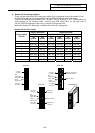
(3) Grid point
The position detector has a Z-phase that generates one pulse per rotation. The 0-point position of this
Z-phase is the grid point. Thus, there is a grid point per rotation of the position detector, and the
machine has many grid points at a set pitch.
The grid point can be set per grid space by setting the grid space (SETUP PARAM. "#2029 grspc").
Thus, multiple grid points can be set per detector rotation.
(4) Grid space
The distance between the grid points is the grid space. The grid space can be set in mm units with the
SETUP PARAM. "#2029 grspc".
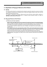
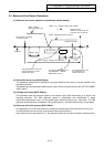
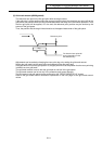
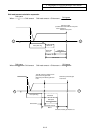
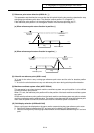
(5) Grid amount
The grid amount expresses the distance from when the near-point detection limit switch leaves the
near-point dog and reaches the grid point (electrical zero point) when the dog-type reference point
return is executed.
The grid amount can be confirmed with "GRID" on the "ALM/DIAG" "SERVO MONITOR (2)" screen of
the setting and display unit.
After setting the grid mask, the grid amount shows the distance from the grid mask OFF to the grid point.